Installation guide, Special instructions, Pwm mode – Veris Industries EP3 SERIES Install User Manual
Page 4: Tristate mode, Tubing length, Analog output, Alarms, Fs point and zero setting, Led blink codes
Z203959-0G
PAGE 4
©2013 Veris Industries USA 800.354.8556 or +1.503.598.4564 / [email protected]
05132
Alta Labs, Enercept, Enspector, Hawkeye, Trustat, Aerospond, Veris, and the Veris ‘V’ logo are trademarks or registered trademarks of Veris Industries, L.L.C. in the USA and/or other countries.
TM
EP3
INSTALLATION GUIDE
SPECIAL INSTRUCTIONS
PWM Mode
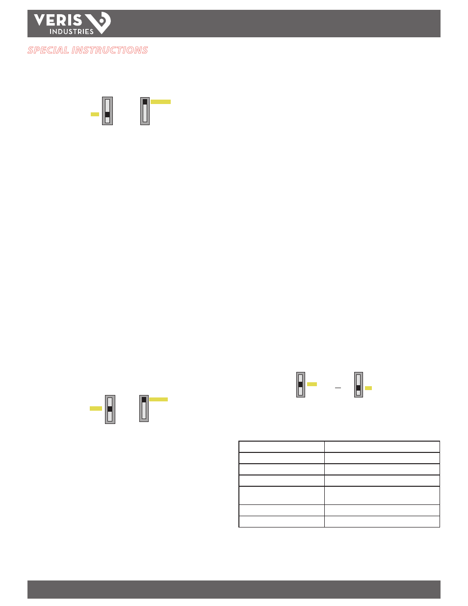
To set the minimum pulse value, adjust the Input and Setting switches as shown:
4-20mA
Voltage
Tristate
PWM
Network
Control
INPUT
Tristate Timing
Network
FS Point
Zero
RUN
SETTING
"LO" momentarily appears on the LCD, indicating that the minimum pulse width is
being set. Use the (+) and (-) buttons to increase or decrease this value. To set the
maximum pulse width push both buttons simultaneously. "HI" momentarily appears,
indicating that the maximum pulse width is being set. Push both buttons to toggle
between the "HI" and "LO" settings. To save these settings, move the Setting slide
switch to RUN.
If the controller receives a pulse that is shorter than the minimum pulse width, the
output goes to 0% of the range set with the zero and span settings. If the controller
sees a pulse that is the same or longer than the maximum pulse width, the output
goes to 100% of the range selected with the zero and span settings.
In this example the minimum pulse width is set to 0.60 sec, the maximum is set to 10
sec, zero is set to 0, and span is set to 10 psi. Assume the controller receives a pulse of
5 sec duration:
Pulse range = 10 sec – 0.60 sec = 9.4 sec
Pressure range = span – zero = 10 – 0 = 10
Output = (5 / 9.4) x 10 = 5.3 psi
Tristate Mode
Traveltime is defined as the contact closure time required to go from zero to full scale.
If traveltime is set to 10 seconds and the TRISTATE 1 input is connected to ground for 5
seconds, the output is 50%. If the input is connected to ground for another 5 seconds,
the output is 100%. If TRISTATE 2 (the decreasing input) is grounded for 10 seconds,
the products output return to 0%.
To set the travel time, adjust the Setting and Input switches as shown:
4-20mA
Voltage
Tristate
PWM
Network
Control
INPUT
Tristate Timing
Network
FS Point
Zero
RUN
SETTING
Press the (+) or (-) buttons to increase or decrease the travel time. Minimum travel
time is 1 second; maximum is 600 seconds. To save these settings, move the Setting
slide switch to RUN. The device's internal counters measure the contact closure time
with 100 Hz resolution.
Note: If Tristate input is to be operated by a triac output (Veris AA49), use an AC relay
to provide a dry contact closure to the EP3 input.
Tubing Length
Minimum tubing length is 15 feet or an equivalent volume of 2.2 cubic inches.
Shorter tubing lengths cause the unit to oscillate.
Analog Output
The output is generated from the branch pressure. It is calculated as follows:
FS = Full Scale Point
Zero = Zero setting
In volt mode:
Pressure = (10 / (FS - Zero)) * Voltage + Zero
Voltage = (Pressure - Zero) / (FS - Zero) * 10
In current mode:
Pressure = (FS - Zero) * ((Current - 4) / 16) + Zero
Current (in mA) = ((Pressure - Zero) / (FS - Zero)) * 16 + 4
Examples:
Zero setting = 5 psi; Span = 20 psi; Branch pressure = 16 psi
Volt mode: Voltage = ((16 - 5) / (20 - 5)) * 10 = 7.33 V
Current mode: Current = ((16 - 5) / (20 - 5)) * 16 + 4 = 15.73 mA
Alarms
Auto Mode: Alarm contacts are closed in normal operation and are open when no
power is applied or when the device is in an alarm state.
Manual Mode: Alarm contacts are open in manual mode setting and closed for
normal operation. Move the P-LOSS/MAN jumper to the manual mode setting. You
do not need to power cycle the product after moving jumpers or the Auto/Manual
switch.
Pressure Loss Alarm: Contacts open when the branch pressure falls and stays below
20% of the desired pressure for a period of 2 minutes.
FS Point and Zero Setting
To set the Zero or FS point, move the SETTING slide switch from Run to Zero or FS
point setting, respectively.
Tristate Timing
Network
FS Point
Zero
RUN
SETTING
Tristate Timing
Network
FS Point
Zero
RUN
SETTING
or
The ‘Set’ icon appears on the LCD. Use the (+) and (-) buttons to increase or decrease
the pressure setpoints.
LED Blink Codes
Slow green
Normal operation
Slow green with one fast red
Manual mode alarm (contacts open)
Slow green with two fast reds
Pressure loss alarm active (contacts open)
Slow red
SETTINGS slide switch not in Run position
Two fast reds
Settings slide switch not in Run position and Alarm
(contacts open)
Three fast reds
Over-voltage or over-current fault
Four fast reds
Over pressure on branch side; over 25 psi.