Veris Industries VTD2P-F50 Install User Manual
Vtd2p-f50, Notice, Danger
ZL0008-0C
PAGE 1
©2012 Veris Industries USA 800.354.8556 or +1.503.598.4564 / [email protected]
05122
Alta Labs, Enercept, Enspector, Hawkeye, Trustat, Veris, and the Veris ‘V’ logo are trademarks or registered trademarks of Veris Industries, L.L.C. in the USA and/or other countries.
TM
RELAYS
INSTALLATION GUIDE
Time Delay, Multi-Function DPDT Relay
Installer’s Specifications
Operating Range
85% to 110% of nominal voltage
Drop-Out Voltage Threshold
15% of nominal voltage
Expected Relay Life
Electrical (resistive @ rated current) 100,000 cycles;
Mechanical
(unpowered) 10,000,000 cycles
Dielectric Strength
1000VAC (RMS)
Operating Temperature
-20°C to 55°C (-4 to 131°F)
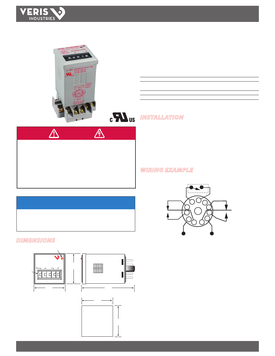
VTD2P-F50
VTD2P-F50
DIMENSIONS
NOTICE
• This product is not intended for life or safety applications.
• Do not install this product in hazardous or classified locations.
• The installer is responsible for conformance to all applicable codes.
• Mount this product inside a suitable fire and electrical enclosure.
INSTALLATION
Disconnect and lock out all power sources before beginning the
installation.
1. Connect relay contacts.
2. Secure the enclosure and reconnect power.
HAZARD OF ELECTRIC SHOCK, EXPLOSION, OR ARC FLASH
• Follow safe electrical work practices.
See NFPA 70E in the USA, or applicable local codes.
• This equipment must only be installed and serviced by qualified electrical personnel.
• Read, understand and follow the instructions before installing this product.
• Turn off all power supplying equipment before working on or inside the equipment.
• Use a properly rated voltage sensing device to confirm power is off.
DO NOT DEPEND ON THIS PRODUCT FOR VOLTAGE INDICATION
Failure to follow these instructions will result in death or serious injury.
DANGER
A-ON DELAY
B-REPEAT
C-INTERVAL
D-OFF DELAY
E-ONE SHOT
TIME
BASE
TIME SET
RED LED
LAMP INDICATOR
Positive position
thumb wheel adjustments
A
S
0
0
0
VERIS INDUSTRIES
1-800-354-8556
VTD2P-F50
1.87"
(47mm)
1.80"
(45mm)
1.80"
(45mm)
3.47"
(88mm)
1.87"
(47mm)
PANEL CUTOUT
FOR PANEL MOUNTING
WIRING EXAMPLE
5 6 7
8
9
11
10
1
2
3
4
INPUT
EXTERNAL CONTROL SWITCH