Veris Industries Badger 310 Install User Manual
Page 4
Data Industrial
Model 310 Installation Guide
4
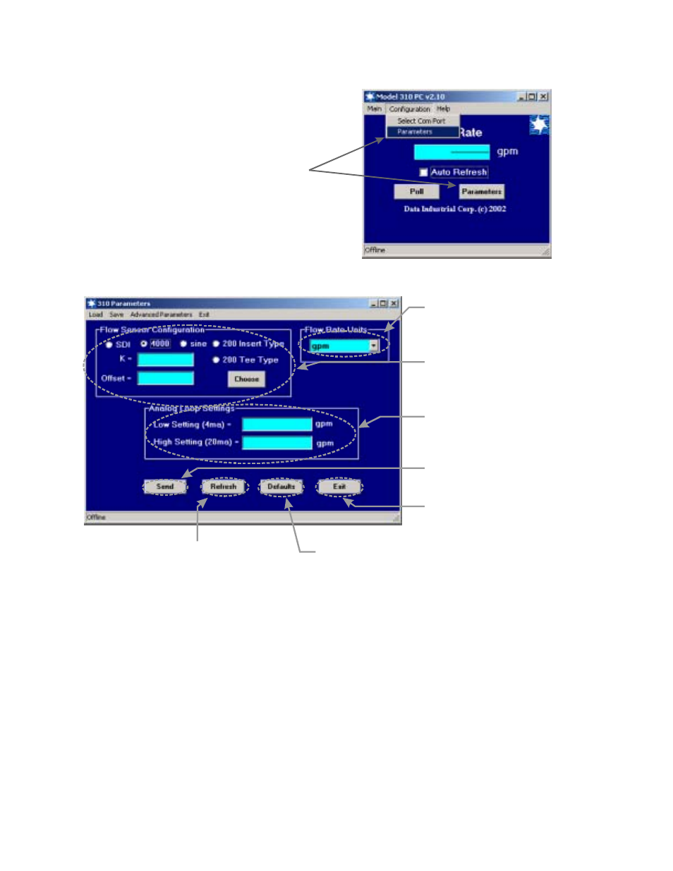
6. Program using diagram below as a reference.
Note #1
Sdi - If the SDI sensor type is selected the required K and offset values can be found the the SDI
owners manual.
4000 - If the 4000 sensor type is selected, click the choose button and select the sensor from the pull
down box that appears.
Sine - Provided for connection to sensors which have a sine wave output. Please consult sensor
manufacturer for the calibration settings.
200 Insert Type - If the 200 Insert Sensor type is selected the required K and offset can be found the
the 200 owners manual or if the manual is not handy the calculate button can be pushed and an inside
pipe diameter can be entered and once calculate is pressed a K and offset will automatically be entered
in.
200 Tee Type - If the 200 tee type is selected, click the choose button and select the sensor from the
pull down box that appears.
To go to calibration settings
screen select "Parameters"
from either place shown
5. Open the Parameters Screen as shown below.
Step #1
Select Flow Rate Units.
Step #2
See Note #1
Select Sensor Type and
Enter K and offset numbers.
Step #3
Enter 4mA Rate and
20mA Rate.
Step #4
Send
Press
to transmit
calibration data to the 310.
Press to refresh the parameters
screen with the current 310 settings.
Press to restore the factory defaults
To save the factory defaults Send
must be pressed before values take effect.
Step #5
Press to exit Parameters screen and
go back to the main screen.