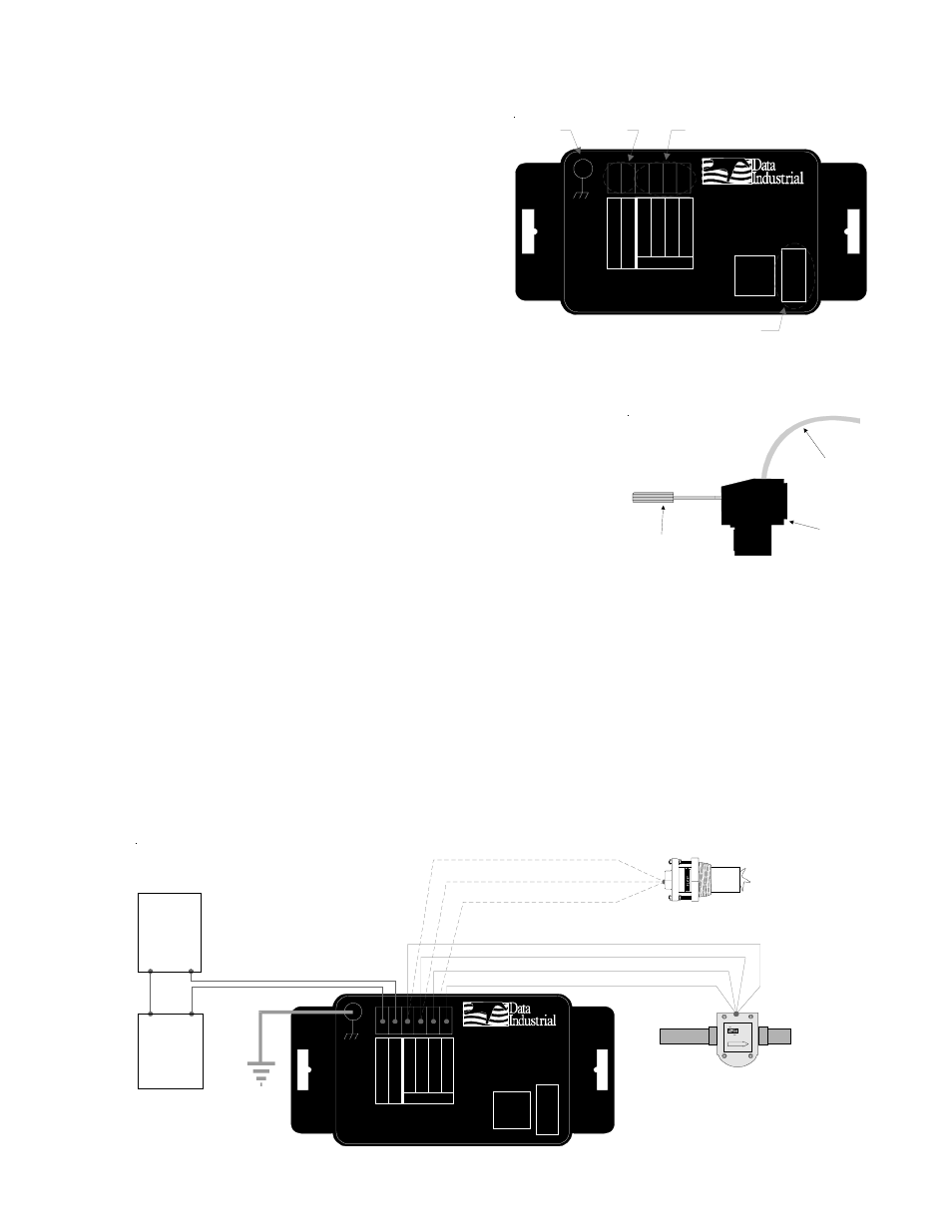
Model 310 electrical installation, Data industrial model 310 installation guide 2, Figure 3: model 310 terminal locations – Veris Industries Badger 310 Install User Manual
Page 2: 24vdc power supply, Analog input device
Data Industrial
Model 310 Installation Guide
2
Model 310 Electrical Installation
Per standard wiring practices, the loop power must be
off before making any wire connections. The terminal
strips have removable plug-in connectors to make
wiring easier.
1. Refer to Figure 3 for terminal connections.
2. As shown in figure 4, connect loop power supply
positive (+) to Model 310 terminal marked 4-20mA
loop (+).
3. Connect terminal marked 4-20mA loop (-) of
Model 310 to positive (+) analog terminal of input
device (Chart Recorder, PLC, etc.).
4. Connect negative (-) analog terminal of input device to loop power
supply negative (-).
5. If Wiring a Series 200 sensor, connect the red wire (signal) to
Signal (+) terminal, black wire (common) to Signal (-) terminal and
the shield to Shield Ground terminal (Disregard shield for the IR
sensors).
If Wiring a Series 4000 sensor, connect the clear wire (signal) to
Signal (+) terminal, black wire (common) to Signal (-) terminal,
shield wire to Shield Ground terminal, and red wire (power) to Power (4000 only) terminal.
If wiring to a sine wave output sensor consult factory.
6. For maximum EMI Protection, connect Model 310 ground lug to panel ground. See Note #1
7. Ensure that all connections are tight, then plug connector into header.
Note #1:
Included with every Model 310 is a 310IK kit containing a screw, lock washer and ground lead to
connect the Model 310 to Earth Ground. This will help prevent electrical interference from
affecting the Model 310s normal operation.
Figure 4: Model 310 Wiring to Analog Loop and Series 200 or Series 4000
Figure 3: Model 310 Terminal Locations
TI)Ã"
®
Tr ÃD
Industrial
4
-20
m
A
Lo
op(
-)
4-
20
m
A
Lo
o
p
(+
)
S
h
ie
ld
G
rou
nd
P
o
w
e
r (4
0
0
0
o
n
ly
)
Hqry)Ã"
Q t hhiyr
6hyt
U hvr
',&
&RPP
3RUW
S
ig
nal (
-)
S
igna
l (
+
)
Mattapoisett, MA 02739
Ground
Lug
Analog
Output
Sensor
Input
DIC
Communications Port
TI)Ã"
®
Tr ÃD
Industrial
4
-20
m
A
Loop(
-)
4-
20m
A
L
oop(
+
)
S
h
ie
ld
G
round
P
o
w
e
r (
4
000
on
ly
)
Hqry)Ã"
Q t hhiyr
6hyt
U hvr
',&
&RPP
3RUW
S
igna
l (
-)
S
ig
nal (
+
)
Mattapoisett, MA 02739
24Vdc
Power
Supply
+
-
Analog
Input
Device
+
-
Red
Black
White(Clear)
D a t a
I n d u s tr i a l
F L O W
4 0 0 0 S e r ie s
Shield (if applicable)
Series 4000
Sensor
Series 200
Sensor
Red
Black
Shield
Side View - Typical 300 Series
Removable Connector Wiring
3/32” Flathead
Screwdriver
Series 300
Connector
Wire