Caution, Installation guide, Operation – Veris Industries H614 Install User Manual
Page 2: Status leds, Troubleshooting, Dimensions, H614, For load currents less than sensor minimum rating
Z206036-0A
PAGE 2
©2012 Veris Industries USA 800.354.8556 or +1.503.598.4564 / [email protected]
09121
Alta Labs, Enercept, Enspector, Hawkeye, Trustat, Veris, and the Veris ‘V’ logo are trademarks or registered trademarks of Veris Industries, L.L.C. in the USA and/or other countries.
TM
INSTALLATION GUIDE
H614
OPERATION
The H614 is a current-sensitive switching device designed for use with VFD systems.
It is equipped with an auto calibration feature that allows the device to distinguish
between a reduced amp draw due to normal changes in frequency and an abnormal
drop due to belt loss or other mechanical failures.
The H614 is designed for HVAC fan and blower systems, as well as some pumping
systems involving consistent viscosity liquids. If an H614 is installed on one phase of
the VFD, it detects changes in that phase that result from the VFD compensating for
changes elsewhere in the system. Alternatively, for increased sensitivity, H614s can
be used on all three phases for immediate detection of amperage changes anywhere
in the system.
A change from the normal amperage and frequency profile in the monitored
conductor will cause the resistance of the FET status output to change state, similar
to the action of a mechanical switch. The status output is suitable for connection to
building controllers or other appropriate data acquisition equipment operating at up
to 30 volts. The H614 requires no external power supply to generate its output.
Performance of the H614 can be optimized through an optional step. When the H614
is first powered and is in Learn Mode, manually cycle through each 5 Hz frequency
band, allowing the VFD to remain at each band for 15 seconds.
NOTES
CAUTION
RISK OF EQUIPMENT DAMAGE
• Derate the product’s maximum current for the number of turns
through the sensing window using the following formula.
Rated Max. Amps ÷ Number of Turns = Max. monitored Amps
e.g. : 100A ÷ 4 Turns = 25 Amps max. in monitored conductor
• Failure to follow these instructions can result in overheating
and permanent equipment damage.
For load currents less than sensor minimum
rating:
Wrap the monitored conductor through the
center window and around the sensor body to
produce multiple turns. This increases the current
measured by the transducer.
4x
0.5A
VERIS INDUSTRIES
Portland, Oregon 97223
1-800-354-85
56
Hawkeye
®
< 1.5 A (Sensor Min.)
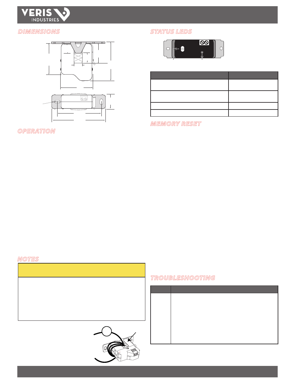
STATUS LEDS
STATUS
RESET
Memory Reset Button
(can be used whether unit is powered or unpowered)
Status LEDs
(left LED = Green; right LED = Red)
Sensor Mode
Status LED Blink Pattern
Learning Mode (first 15 sec of operation after frequency
stabilizes)
Alternating Red/Green (1 per sec.)
On/Off Status only; Learn mode incomplete. VFD system
does not meet abnormal condition detection criteria
Green blink (5 times per sec. after
15 sec of stable frequency)
Status OK
Green blink (1 per sec.)
Alarm
Red blink (1 per sec.)
MEMORY RESET
During setup, the H614 automatically determines the normal amperage and
frequency profile and stores it in nonvolatile memory. The H614 requires a Memory
Reset to clear the nonvolatile memory if any of the following conditions occur:
• The sensor is reinstalled on a different motor.
• The motor is re-sheaved.
• The system is air balanced or air duct restrictions change
• The motor load changes significantly.
To reset the H614:
1. Establish normal operating conditions for the monitored conductor (e.g. clean air
filters, close duct access doors).
2. The Reset switching button has two positions, in and out. Push the button until
there is a noticable click to change the position of this switch. This causes a change
of state, which triggers the Reset function. The nonvolatile memory is erased and
the H614 will enter the Learning mode (LEDs blink red/green) to learn the new
amperage profile of the monitored conductor.
Note: The Reset function can be performed even if the H614 is not
installed on a conductor. Pushing the button (changing the state) will
clear the nonvolatile memory at the next power-up.
Note: For normal operation, this button can be in either in or out
position.
TROUBLESHOOTING
Problem
Solution
No LED or
Incomplete
Learn mode
• Check for amperage in monitored conductor (>1.5 A).
• Check that amperage in the monitored conductor does not exceed sensor
max (150 A).
• Ensure that no more than 30 VAC/DC or 1.0A has passed through the contact.
Voltages or currents above these levels will damage the unit.
• Ensure that sensor core mating surfaces are clean and that the core clamp is
completely closed.
• Ensure that the sensor is operating within specified temperature range.
• Ensure that the sensor has completed Learn mode. If it has not, check circuit
parameters and compliance.
DIMENSIONS
2.5" *
(64 mm)
2.1"
(54 mm)
3.5"
(89 mm)
2.9"
(74 mm)
0.4” x 0.2”
(10 mm x 5 mm)
Slot (2x)
1.2"
(31 mm)
Removable Mounting Bracket
0.7"
(18 mm)
0.5"
(13 mm)
2.1"
(54 mm)
1.0" *
(26 mm)
0.6"
(16 mm)