Veris Industries H614 Install User Manual
Danger, H614, Notice
Z206036-0A
PAGE 1
©2012 Veris Industries USA 800.354.8556 or +1.503.598.4564 / [email protected]
09121
Alta Labs, Enercept, Enspector, Hawkeye, Trustat, Veris, and the Veris ‘V’ logo are trademarks or registered trademarks of Veris Industries, L.L.C. in the USA and/or other countries.
TM
CURRENT MONITORING
INSTALLATION GUIDE
Split-Core Current Switch, Auto Calibrating,
For VFD Applications, 12 to 115 Hz
Specifications
Sensor Power
Induced from monitored current
Amperage Range
1.5 to 150A Continuous
Status Output
N.O. 1.0A@30VAC/DC
Response Time
1 second
Learn Time
15 seconds after frequency ramping stablizes
Frequency
12 to 115 Hz
Temperature Range -15° to 60°C (5° to 140°F)
Humidity Range
10-90% RH non-condensing
Alarm Limits
±20% of learned current in every 5 Hz freq. band
Normal-to-Alarm Status Output Delay
5 sec. max.
Alarm-to-Normal Status Output Delay
1 sec. nominal *
Off Delay
<30 sec (nominal)
Contact Ratings
30VAC/DC, 1A
Insulation Class
600VAC (UL); 300VAC (CE)
Terminal Block Maximum Wire Size
14 AWG
Terminal Block Torque
3.54 to 4.43 in-lbs (0.4 to 0.5 N-m)
Agency Approvals
UL 508, CE: EN61010-1:2001,
Installation
Category III, pollution degree 2
* If the H614 experiences a momentary loss of power, the Alarm-to-Normal output delay may
exceed 1 sec.
Specification Note: For CE compliance, conductor shall be insulated according to IEC 61010-1:2001.
The product design provides for basic insulation only. Use wire with minimum 75°C rated insula-
tion. Do not use the LED status indicators as evidence of applied voltage.
This sensor detects abnormal operation by looking for sudden changes in current across the entire
frequency range. In Learn mode, the sensor calculates a margin 20% above and 20% below the
learned frequency curve. An abnormal condition in the circuit is one that falls outside this margin.
HAZARD OF ELECTRIC SHOCK, EXPLOSION, OR ARC FLASH
• Follow safe electrical work practices. See NFPA 70E in the USA, or applicable local codes.
• This equipment must only be installed and serviced by qualified electrical personnel.
• Read, understand and follow the instructions before installing this product.
• Turn off all power supplying equipment before working on or inside the equipment.
• Use a properly rated voltage sensing device to confirm power is off.
DO NOT DEPEND ON THIS PRODUCT FOR VOLTAGE INDICATION
• Only install this product on insulated conductors.
Failure to follow these instructions will result in death or serious injury.
A qualified person is one who has skills and knowledge related to the construction and
operation of this electrical equipment and the installation, and has received safety
training to recognize and avoid the hazards involved.
NEC2009 Article 100
No responsibility is assumed by Veris Industries for any consequences arising out of the
use of this material.
DANGER
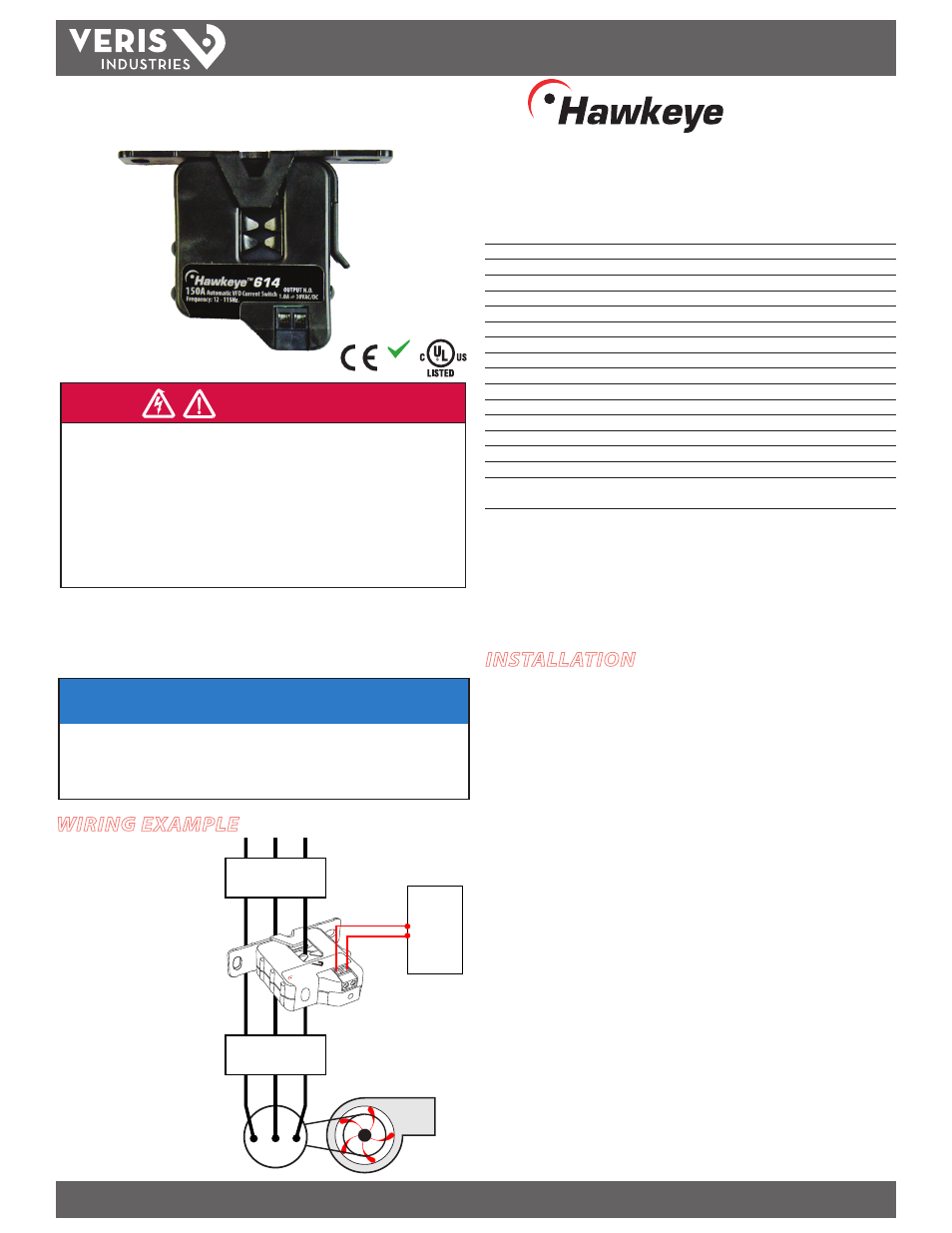
WIRING EXAMPLE
H614
TM
614
NOTICE
• This product is not intended for life or safety applications.
• Do not install this product in hazardous or classified locations.
• The installer is responsible for conformance to all applicable codes.
• Mount this product inside a suitable fire and electrical enclosure.
INSTALLATION
1. Establish normal operating conditions for the VFD (clean filter, normal load, etc.).
2. Disconnect and lock out power to the VFD, the enclosure, and the conductor to be
monitored.
3. Choose a location for the sensor. The monitored conductor must pass through
the center window, and the sensor must be at least ½” from any uninsulated
conductors. Mount the sensor on the load side output conductor of the Variable
Frequency Drive. Do not install on VFD input power conductors. If using a bypass
system, place the H614 between the VFD and the bypass device.
4. Install the mounting bracket in the enclosure using the included screws.
5. Wire the connections between the sensor and the controller.
6. Snap the sensor over the conductor to be monitored. Snap the unit with the
bracket latched securely to ensure proper operation.
7. Restore power to the VFD and the conductor.
8. As the VFD frequency ramps up, the sensor enters Learn mode. The LED will blink
(alternating red-green).
9. 15 seconds after the VFD frequency ramping is complete, the sensor self-
calibration is finished. The LED will blink (green only).
Note: If the VFD current does not change during the Learn mode period, the
sensor will not learn normal conditions. The LED will blink (green, 5 times per
second) to indicate the sensor is in Status Only mode, monitoring the circuit
for on/off status.
NOTE: The H614 is not intended
for use in staged pump or variable
inlet vane applications.
NOTE: (Optional) For added
sensitivity in detecting amperage
changes, use H614 devices on
all three phases of the VFD (see
Operation section for details).
Fan or Pump
CONTROL
DI
Motor
VERIS INDUSTR
IES
Portland, Oregon 97223
1-800-354-8556
Hawkeye
®
614
VFD
BYPASS DEVICE
(if used)
RoHS
Compliant