Installation guide, Wiring operation configuration, Veris industries – Veris Industries PW2 SERIES Install User Manual
Page 2: Pw2 series, Polarity insensitive
VERIS INDUSTRIES
™
inStallation GUiDe
PW2 SerieS
Z204201-0G
PAGE 2
©2010 Veris Industries USA 800.354.8556 or +1.503.598.4564 / [email protected]
08102
Alta Labs, Enercept, Enspector, Hawkeye, Trustat, Veris, and the Veris ‘V’ logo are trademarks or registered trademarks of Veris Industries, L.L.C. in the USA and/or other countries.
DIGITAL CONTROL
Digital Output
4-20mA IN
POWER SOURCE
12 to 24 VDC
Port Swap/Norm
Bi-Dr/Normal
Slow Avg/Fast Norm
Analog Rev/Norm
Bar/PSI
ZERO
A-High
B-Mid High
C-Mid Low
D-Low
REMOTE
ZERO
4-20mA
Pressure
Range
Settings
Polarity
Insensitive
Default Settings in bold.
Insert jumper to activate
other features.
Model
PW2-03
PW2-04
PW2-05
A
50
100
250
B
25
50
125
C
10
20
50
D
5
10
25
Model
PW2-03
PW2-04
PW2-05
A
3.45
6.89
17.24
B
1.72
3.45
8.62
C
0.69
1.38
3.45
D
0.34
0.69
1.72
Range (PSI)
Range (bar)
HI PORT
100 psi
100 psi
50 psi
50 psi
0 psi
LO PORT
0 psi
50 psi
50 psi
100 psi
100 psi
4-20mA
+100 psi
+50 psi
0 psi
-50 psi
-100 psi
Bidirectional Operation
Input Conditions
Result
Outputs Read
DP
20mA
16mA
12mA
8mA
4mA
Output is mA only.
Example: PW2-04
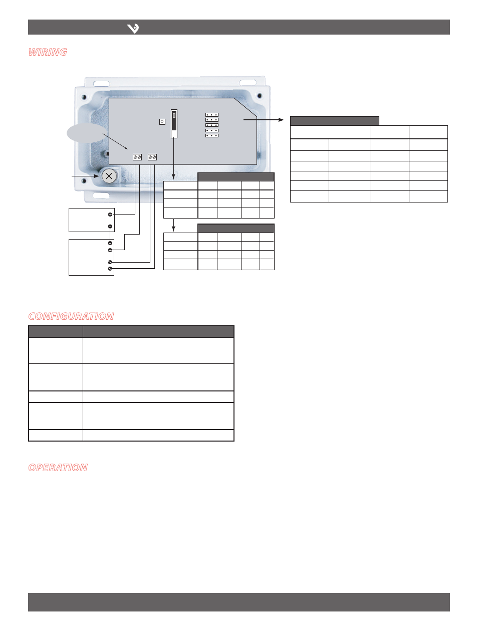
Wiring
oPeration
configuration
Jumper
Notes
Port Swap/Norm
Reverses polarity of the pressure ports (i.e. makes the LO port
operate as the HI port and vice versa); used when the sensor is
incorrectly plumbed.
Bi-Dr/Normal
Normal: 0 to F.S. pressure
Bidirectional: -F.S. pressure to +F.S. pressure; output reads 1/2 when
pressure is zero.
Slow Avg/Fast Norm
Slow mode provides 5 second averaging for surge damping.
Analog Rev/Norm
Normal: output increases as pressure increases;
Reverse: output is maximum when pressure differential is zero and
decreases as pressure increases.
Bar/PSI
Select output units.
Optional: Connect Zero terminals to digital output (contact
closure) of control system.
Caution: Zero input is for dry-contact only. Do not apply voltage to
the Zero terminals.
Range: Use the Range switch to select
F.S. differential pressure.
Auto-Zero: Press and hold the Zero button for 2 seconds or provide contact closure on
the auxiliary ‘Remote Zero’ terminal to reset the output to zero pressure. To protect
the device from accidental zeroing, this feature is only enabled when the detected
pressure is within 5% of factory calibration.
Note: Use of a
housing grounding
screw is required
for CE applications