Veris Industries PH SERIES Install User Manual
Ph series, Notice, Wet media pressure transducer
Z202149-0K
PAGE 1
©2012 Veris Industries USA 800.354.8556 or +1.503.598.4564 / [email protected]
03122
Alta Labs, Enercept, Enspector, Hawkeye, Trustat, Veris, and the Veris ‘V’ logo are trademarks or registered trademarks of Veris Industries, L.L.C. in the USA and/or other countries.
TM
ENVIRONMENTAL SENSORS
INSTALLATION GUIDE
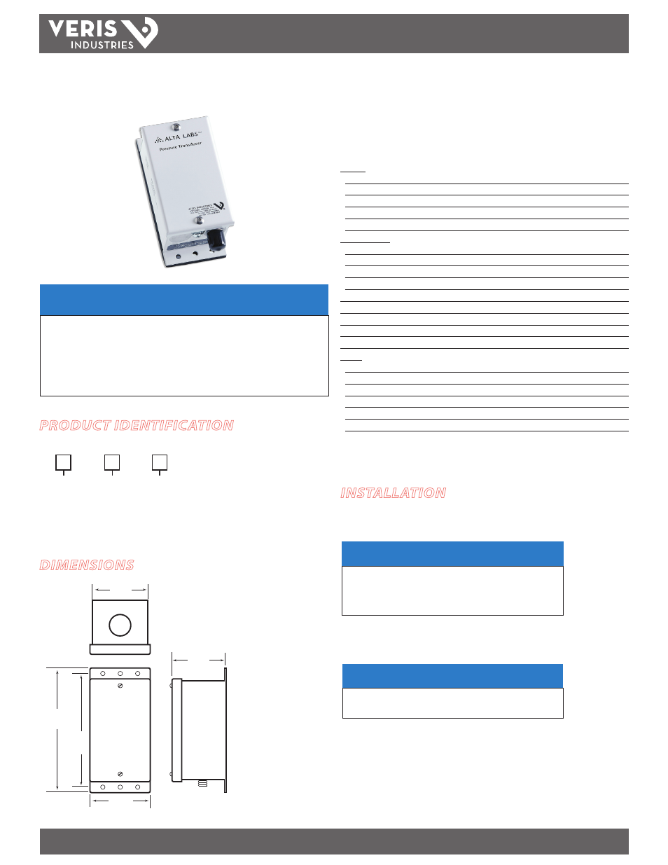
Wet Media Pressure Transducer
Installer’s Specifications
Product:
Input Power
12 to 30 VDC/24 VAC
Output
3-wire transmitter; user selectable 4-20mA (clipped and capped)/0-5V/0-10V*
Accuracy
±1% F.S. Combined linearity, hysteresis, and repeatability
Surge Damping
Electronic; 5-second averaging
Test Mode
Overrides output to full-scale (20 mA, 5 V, 10 V)
Pressure Ranges:
0-100 psi
25/50/100 psig switch selectable
0-250 psi
62.5/125/250 psig switch selectable
0-500 psi
125/250/500 psig switch selectable
0-1000 psi
250/500/1000 psig switch selectable
Operating Environment
-10° to 55°C (-4° to 130°F); 0 to 90% RH, non-condensing
Long Term Stability
±0.25% per year
Zero Adjust
Pushbutton auto-zero and digital input (2-pos terminal block)**
Status Indication Dual-color LED: Green = Normal, Red = Overpressure, Flashing Red = Fault
Housing Material
White powder-coated steel
Sensor:
Media Compatibility
Media compatible with 17-4 PH stainless steel
Proof Pressure
Max. 2x F.S. range
Burst Pressure
Max. 5x F.S. range
Temperature Compensated Range
0° to 50°C (32° to 122°F)
Media Temperature Limits
-20° to 85°C (-4° to 185°F); 0 to 90% RH non-condensing
Fittings
1/4” NPT male thread, 17-4 PH stainless
* Minimum input voltage for 4-20 mA operation: 250 ohm loop (1-5V) = 12 VDC; 500 ohm loop
(2-10V) = 15 VDC. Minimum input voltage for 0-10V operation: 15 VDC
** This feature is enabled only when the detected pressure is within 5% of factory calibration.
PH SerieS
PH SerieS
DIMENSIONS
NOTICE
• This product is not intended for life or safety applications.
• Do not install this product in hazardous or classified locations.
• Read and understand the instructions before installing
this product.
• Turn off all power supplying equipment before working on it.
• The installer is responsible for conformance to all applicable codes.
PRODUCT IDENTIFICATION
INSTALLATION
1. Connect transmitter to control system and power supply. PH Series are 3-wire
sourcing type transmitters.
NOTICE
This product utilizes a half-wave rectifier power supply. If a
transformer is to be used to power this product, the transformer
must not be used to power other devices utilizing non-isolated
full-wave power supplies. Failure to comply may result in
reduced accuracy.
2. (Optional) Connect TARE (zero) terminals to digital output (contact closure) of
control system.
NOTICE
TARE input is for dry-contact. Do not apply voltage to TARE (zero)
terminals. Failure to comply may result in equipment damage.
3. Use jumper JP1 to select voltage (V) or current (mA) mode.
4. Use jumper JP2 to select 0-10 V or 0-5 V output span (Voltage mode only).
5. Use jumper JP3 to select slow or fast mode. Slow mode provides 5-second
averaging for surge dampening.
6. Select appropriate full-scale range using the slide switch.
2.25"
(57 mm)
2.2"
(56 mm)
4.5"
(115 mm)
5.1"
(129 mm)
2.5"
(62 mm)
NIST
N = NIST
X = None
Range
07 = 0-100 psig
08 = 0-250 psig
09 = 0-500 psig
10 = 0-1000 psig
PH S
= Standard