Current monit oring, Dimensional drawings, Application/wiring diagrams – Veris Industries H939 SERIES Datasheet User Manual
Page 2: Ordering information, Accessories
current monit
oring
800.354.8556
+1 503.598.4564
www.veris.com
MODEL AMPERAGE
RANGE
STATUS OUTPUT
(max.)
MIN. TRIP
POINT
RELAY
TYPE
RELAY
COIL
HOUSING STATUS
LED
RELAY
POWER LED
UL
H739
1 - 135A
N.O. 0.2A@120VAC/DC
1A or less
SPST, N.O.
24VAC/DC
Solid-core
n
n
n
H749
1 - 135A
1A or less
SPDT
24VAC/DC
Solid-core
n
n
n
H939
2.5 - 135A
2.5A or less
SPST, N.O.
24VAC/DC
Split-core
n
n
n
H949
2.5 - 135A
2.5A or less
SPDT
24VAC/DC
Split-core
n
n
n
H959
2.5 - 135A
2.5A or less
SPST, N.O.
12VDC nom.
Split-core
n
n
n
H739/H749
H939/H949/H959
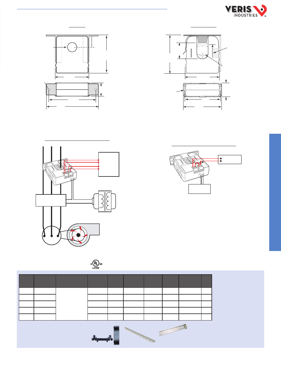
DIMENSIONAL DRAWINGS
Relay Controlled Directly by Status Contacts
APPLICATION/WIRING DIAGRAMS
Start/Stop Monitoring of Fan /Pump Motors
ORDERING INFORMATION
* Terminal block may extend up to 1/8” over the height dimensions shown.
0.2” x 0.15”
slot (2x)
1.1" *
(27 mm)
2.8"
(68 mm)
0 0.7"
(19 mm)
0.9"
(23 mm)
3.0" **
(75 mm)
Removable/Adjustable Mounting Bracket
3.8"
(95 mm)
4.2"
(106 mm)
Removable Mounting Bracket
Self-gripping Iris
1.0”
(25 mm)
0.8”
(21 mm)
1.1”
(26 mm)
**3.1”
(79 mm)
2.8”
(70 mm)
Ø 0.3”
(8 mm)
1.4”*
(36 mm)
2.5”
(64 mm)
3.0”
(76 mm)
Bracket can
be mounted
on three sides
for added
installation
flexibility.
Fan or Pump
CONTROLLER
Motor
CONTACTOR
DI (Status)
DO (Relay
Coil)
CONTROL
POWER
RELAY LOAD
Relay Coil
Power Source
ACCESSORIES
DIN Rail Clip Set (AH01)
DIN Rail (AV01) and DIN Stop Clip (AV02)
AH01
AV01
AV02
HQ0001761.C 01131