Rel ay s, Dimensional drawing, Amperage derating for temperature – Veris Industries VS861 SERIES Datasheet User Manual
Page 2: Load considerations, Application/wiring example ordering information, Input output ac input controller wiring diagram, Load, 10 amp style, Rohs, 8 amp style
REL
AY
S
800.354.8556
+1 503.598.4564
www.veris.com
0.7”
(18mm)
3.5”
(90mm)
4.2”
Ø .19”
(5 mm)
(107mm)
1.4”
(36mm)
2.6” MAX
(65mm)
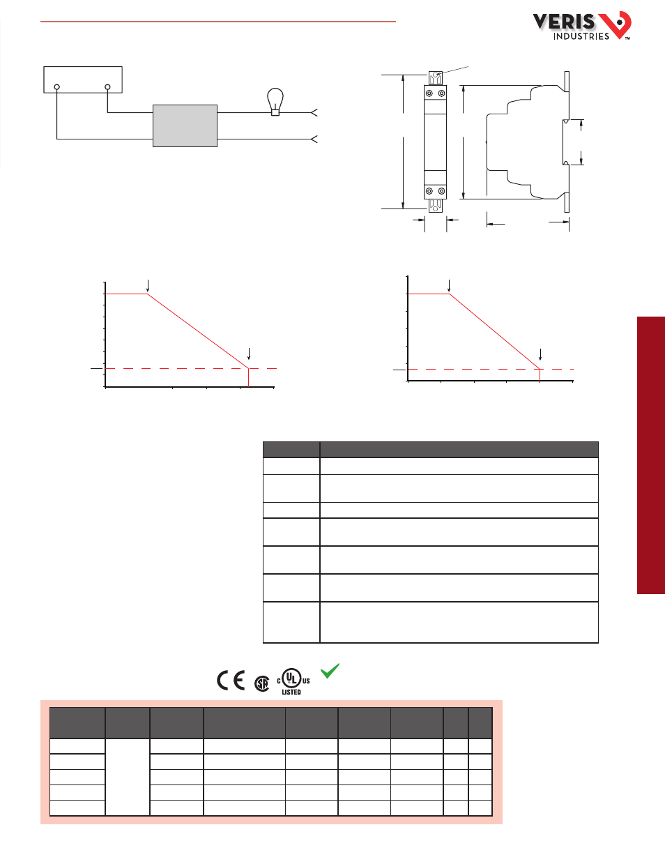
DIMENSIONAL DRAWING
+
+
INPUT
OUTPUT
AC INPUT
CONTROLLER
WIRING DIAGRAM
SSR
–
–
LOAD
MODEL
RELAY
AMPERAGE
RATING
INPUT VOLTAGE
SWITCHING
DEVICE
SWITCHING
VOLTAGE
SWITCHING
TYPE
UL
CE
VS861210DC
SPST, N.O.
10A
3-32VDC
SCR
24-280VAC
Zero Cross
n
n
VS861210AC
10A
90-280VAC, 80-140VDC
SCR
24-280VAC
Zero Cross
n
n
VS861208DC
8A
3-32VDC
Triac
24-280VAC
Zero Cross
n
n
VS861208AC
8A
90-280VAC, 80-140VDC
Triac
24-280VAC
Zero Cross
n
n
VS861208DD
8A
3.5-32VDC
MOSFET
3-150VDC
DC Switching
n
n
0
2
4
6
8
10
12
0
20
40
60
80
100
Max. Ambient Temp (°C)
25˚
80˚
10 AMP STYLE
1.8*
*Cut off current
Lo
ad
C
ur
re
nt
(A
m
ps
R
M
S)
0
1
2
3
4
5
6
7
8
9
0
20
40
60
80
100
Max. Ambient Temp (°C)
25˚
85˚
8 AMP STYLE
1.5*
*Cut off current
Lo
ad
C
ur
re
nt
(A
m
ps
R
M
S)
AMPERAGE DERATING FOR TEMPERATURE
LOAD TYPE
CAUTIONARY ACTION
All load types
Verify that the inrush current does not exceed the surge specifications of the SSR.
Steady-state
resistance
Follow standard thermal considerations.
DC (inductive)
Place a diode across the load to absorb surges during turnoff.
Incandescent
lamp
Use a zero voltage turn-on characteristic.
Capacitive
Verify that the rate of current rise capabilities are not exceeded. Zero voltage turn-on is an
effective method for limiting this rate.
Motors and
Solenoids
Use a current shunt and oscilloscope to examine the duration of the inrush current. Verify
that back EMF does not create an overvoltage situation during turn-off.
Transformers
Use a zero cross turn-on device; verify that the half cycle surge capability is not exceeded.
Rule of thumb: select an SSR with a half cycle current surge rating greater than the
maximum applied line voltage divided by the transformer primary resistance.
LOAD CONSIDERATIONS
The primary concern when using SSRs is improper heat
sinking. The type of load current should be evaluated when
considering an SSR as a switching option. SSRs alone are
not compatible with high inrush currents, but cautionary
measures can be taken in high inrush applications to
increase the SSR’s versatility.
APPLICATION/WIRING EXAMPLE
ORDERING INFORMATION
RoHS
Compliant
HQ0001855.B 01131