Caution, Installation guide, Operation – Veris Industries H922030A Install User Manual
Page 2: Troubleshooting, Scaling, Wiring
6%2)3
INSTALLATION GUIDE
H922xxxA
Z204089-0C
PAGE 2
©2009 Veris Industries USA 800.354.8556 or 503.598.4564 / [email protected]
03095
Alta Labs, Enercept, Enspector, Hawkeye, Trustat, Veris, and the Veris ‘V’ logo are trademarks or registered trademarks of Veris Industries, L.L.C. in the USA and/or other countries.
opEration
The H922xxxA Series is a set of current-sensitive devices that monitors current
(amperage) in the conductor passing through. Each device has a fixed output of either
30, 60, or 120 Amps (non-selectable). The status output is suitable for connection to
building controllers or other appropriate data acquisition equipment operating at up
to 30 volts. The H922xxxA Series requires no external power supply to generate its
output.
troublEshooting
Problem
Solution
No Reading at Controller
• Check for amperage in monitored conductor (> 2.5A)
• Assure that sensor core mating surfaces are clean and
that the core clamp is completely closed.
• Check the polarity of the circuit.
scaling
SENSED AMPS
30/60/120 A
0 VDC
0A
5 VDC
SENSOR OUTPUT
DDC
CONTROLLER
COMM
0-5VDC Input
CAUTION: Consult
instructions prior
to installation
!
Use min. 75º C insulated conductor
ig20
OUTPUT
0-5VDC
+
–
+
–
Self-Powered Output
Wiring
The amperage range is indicated on the product label, near the terminal screws. The
H922 Series is available with three choices: 30, 60, or 120 Amps.
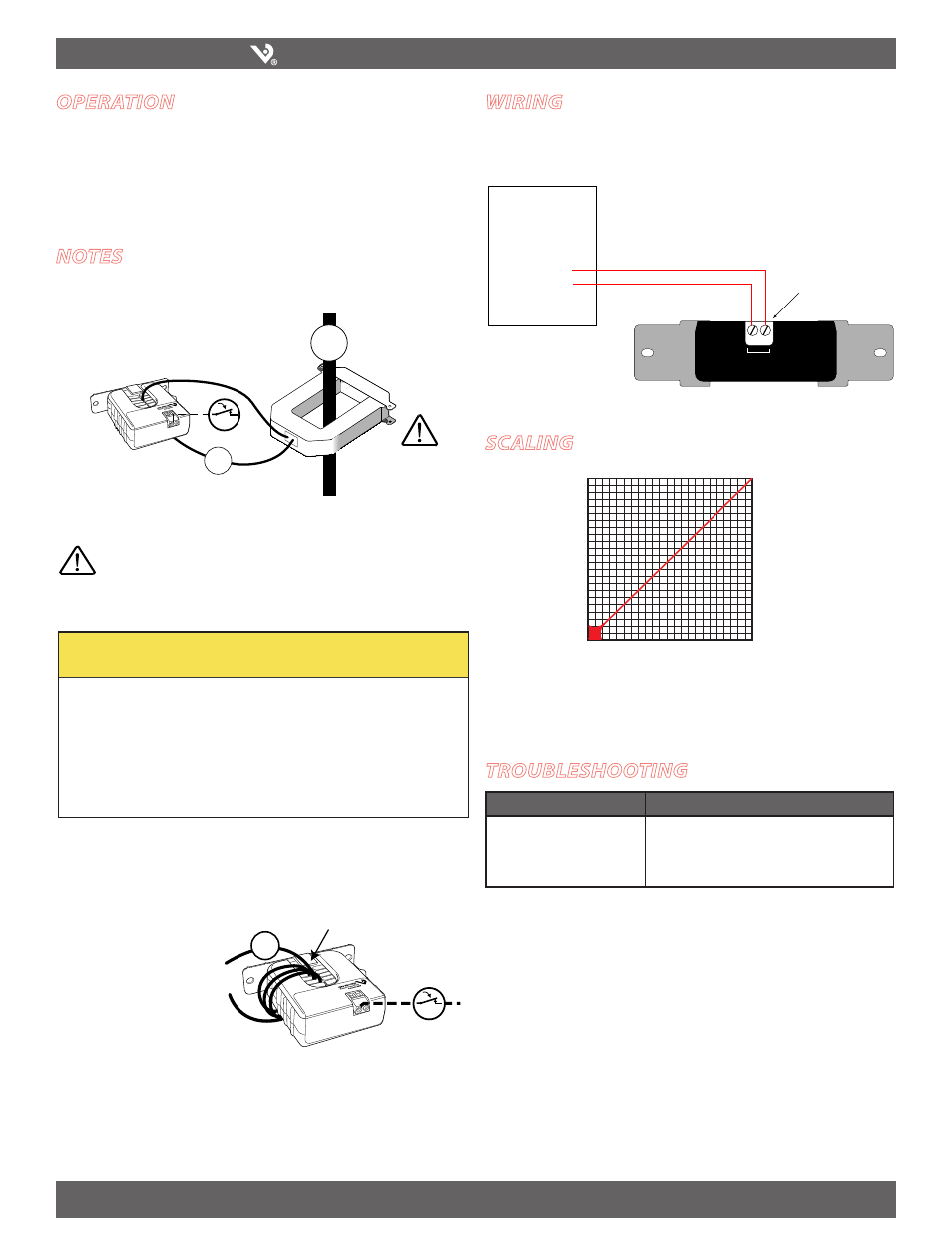
notEs
For load currents less than sensor minimum rating:
Wrap the monitored conductor through the center hole and around the sensor body
to produce multiple turns through the "window." This increases the current measured
by the transducer.
1A
4x
DANGER: 5A CTs can present hazardous voltages.
Install CTs in accordance with manufacturer's instructions.
Terminate the CT secondary before applying current.
H68xx-5A CT
240A
300A:
5A
4A
> 30/60/120A (Sensor max.)
For load currents greater than sensor maximum rating:
Use a 5 Amp (H68xx series) Current Transformer (CT) as shown.
CAUTION
RISK OF EQUIPMENT DAMAGE
t %FSBUFUIFQSPEVDUTNBYJNVNDVSSFOUGPSUIFOVNCFSPGUVSOT
UISPVHIUIFTFOTJOHXJOEPXVTJOHUIFGPMMPXJOHGPSNVMB
3BUFE.BY"NQT/VNCFSPG5VSOT.BYNPOJUPSFE"NQT
FH"5VSOT"NQTNBYJONPOJUPSFEDPOEVDUPS
t 'BJMVSFUPGPMMPXUIFTFJOTUSVDUJPOTDBOSFTVMUJOPWFSIFBUJOH
BOEQFSNBOFOUFRVJQNFOUEBNBHF
Controller must be
programmed to account for the
extra turns. e.g., if four turns
pass through the sensor (as
shown) the normal controller
reading must be divided by 4.
< 2 A (Sensor Min.)