Lighting c ontr ols, Application/wiring diagrams, Specifications - aa47 – Veris Industries MSC SERIES Datasheet User Manual
Page 2: Specifications - aa48, Ordering information
LIGHTING C
ONTR
OLS
800.354.8556
+1 503.598.4564
www.veris.com
Sensing
Technology
U = Ultrasonic
D = PIR + Ultrasonic
P= Passive Infrared (PIR)
MSC
Coverage
1000 = 1000 Sq. Ft. (Passive Infared only)
2000 = 2000 Sq. Ft. (Ultrasonic or Dual technology only)
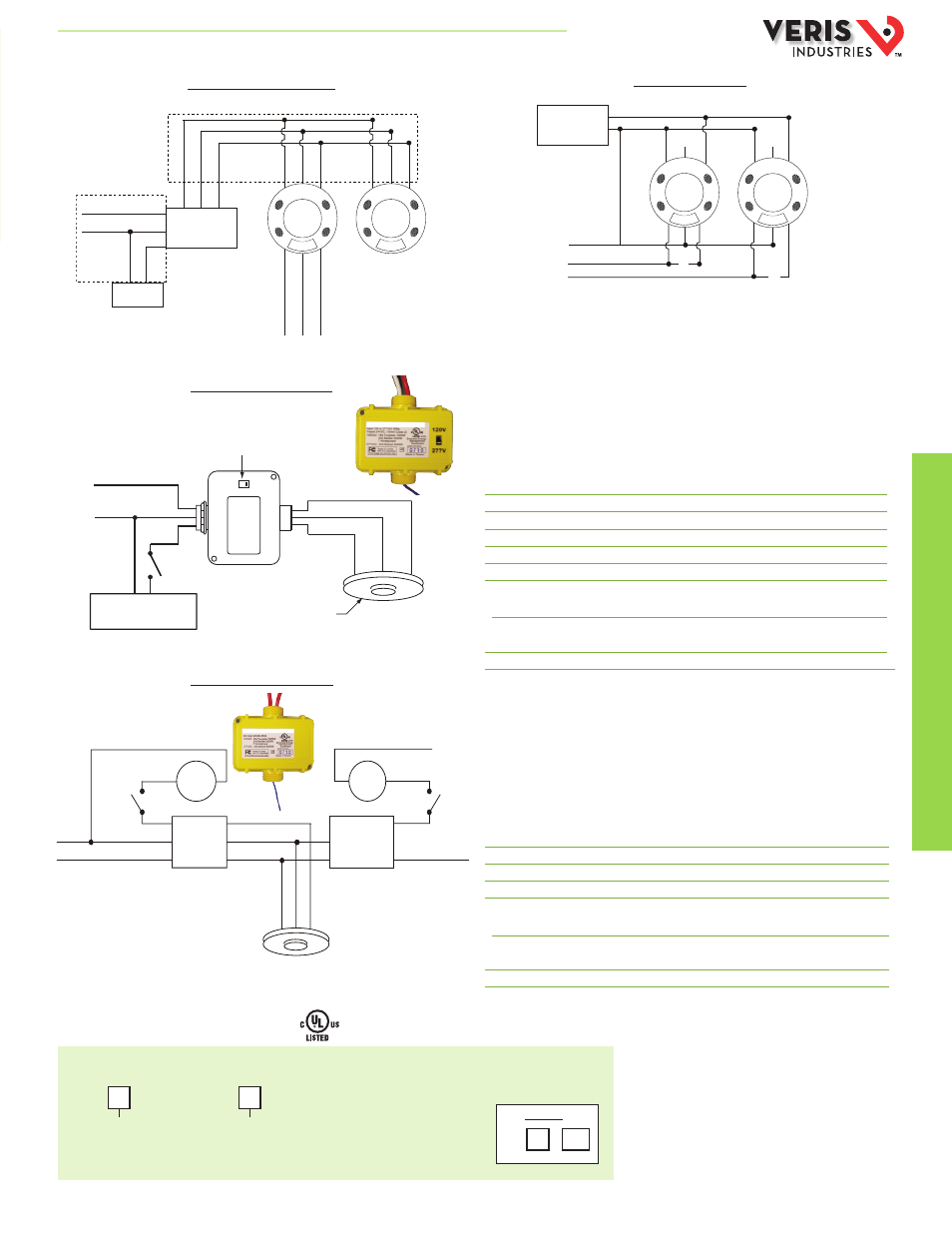
APPLICATION/WIRING DIAGRAMS
System Diagram Using AA48
System Diagram Using AA47
Local Line-Power Control MSC
Building Control Panel
AA48 Auxilary Relay (Optional)
AA47 Line-Switching Power Pack
The AA47 Line-Switching Power Pack provides local switching capability to control
loads at a signal from MSC Series occupancy sensors, independent of any connection
to building control systems. The AA47 routes 120/277VAC, 60 Hz line power directly
to a Form A relay contact (SPST) to control a load and generates full-wave, 24VDC
to power up to four MSC sensors (dependent on model). The AA47 can be mounted
either inside or outside an electrical box, and sensor power can be routed via
plenum-rated cable to the sensor(s).
SPECIFICATIONS - AA47
Storage Temperature
-29° to 65°C (-20° to 150°F )
Operating Temperature
0° to 40°C (32° to 104°F)
Maximum Humidity 90% RH noncondensing
AC Power Input 120/277VAC ± 10%, 60 Hz
Output Voltage 24VDC
Output Current
100mA max.
Relay Contacts:
Horsepower Rating 1HP@120V
Switching Capacity 120VAC, 60 Hz; 15A tungsten 1800W
277VAC, 60 Hz; 20A Ballast
Dimensions 3.2” (81.3 mm) x 3” (76.2 mm) x 1.75” (44.5 mm)
The AA48 Auxiliary Relay is a low-voltage relay device for expanding the switching
capacity of an AA47. It can be used to control loads connected to additional circuits
in response to a signal from a connected sensor. It is essentially a relay with a SPST
output controlled directly by the occupancy sensor. The auxiliary relay can be
mounted inside or outside of an electrical junction box.
SPECIFICATIONS - AA48
Storage Temperature
-29° to 65°C (-20° to 150°F )
Operating Temperature
0° to 40°C (32° to 104°F)
Maximum Humidity
90% RH noncondensing
Control Input
24VDC, 36mA nominal
Relay Contacts:
Horsepower Rating 1HP@120V
Switching Capacity
120VAC, 60 Hz; 15A tungsten 1800W
120/277VAC, 60 Hz; 20A ballast
Dimensions
3.2” (81.3 mm) x 3” (76.2 mm) x 1.75” (44.5 mm)
For local line switching
ORDERING INFORMATION
Contact rating:
1A @ 24VDC Resistive
Aux. Relay
Hot
Neutral
Black
White
Red
Blac
k
Blue
Red
Blac
k
Blue
Red
Blac
k
Blue
Red
Or
ange (N.O
.)
Yellow
(Common)
Gr
een (N.C.)
Power Pack
AA47
Load
Class 1
Class 2
Additional
Sensor(s)
(optional)
24VDC
BLK
BLK
RED
RED
COMMON
ORG N.O.
ORG N.O.
GRN N.C.
GRN N.C.
CONTROL IN
CONTROL IN
+24VDC
+
-
or
or
120V
277V
RED
Load
Ext. Override OFF
RED
BLK
BLK
White
Neutral
Hot
BLUE
Control Input
Common
+24VDC
Voltage Selector
Sensor
Line Voltage
120/277VAC
Load
AA47
Power
Pack
AA48 Optional
Auxiliary
Relay
Red
Red
Red
Hot
Neutral
Hot
White
Black
+24VDC (Red)
0VDC (Blk)
Control (Blue)
Override
OFF
Ext. Override
OFF
Load
Load
Sensor
Example:
MSC D 2000
HQ0001801.B 01131