Veris Industries H723HC Install User Manual
Solid-core current transducer, 0-10vdc, Installation guide, Wiring example
6%2)3
CURRENT MONITORING
INSTALLATION GUIDE
Z205458-0A
PAGE 1
©2008 Veris Industries USA 800.354.8556 or 503.598.4564 / [email protected]
09083
Alta Labs, Enercept, Enspector, Hawkeye, Trustat, Veris, and the Veris ‘V’ logo are trademarks or registered trademarks of Veris Industries, L.L.C. in the USA and/or other countries.
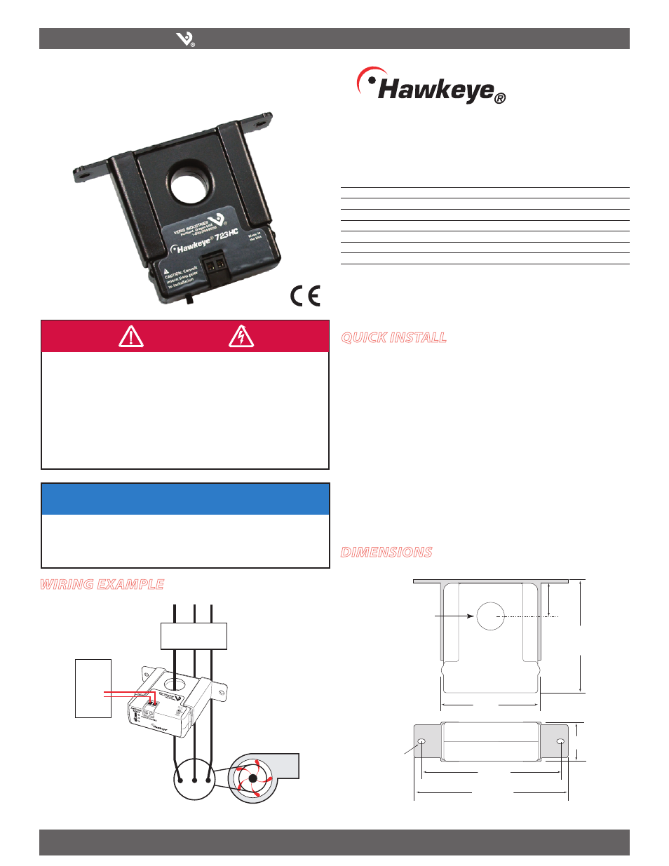
Solid-Core Current Transducer, 0-10VDC
Installer’s Specifications
Amperage Range
0-50/100/200 Amps (slide switch selectable)
Accuracy
±2% F.S. from 10% to 100% of selected range
Output
0-10VDC self powered
Insulation Class
300VAC RMS
Frequency
50-60 Hz
Temperature Range
-15° to 60°C (-5° to 140°F)
Humidity Range
10-90% RH non-condensing
Safety
IEC 61010-1:2001 CAT III
For CE compliance, conductor shall be insulated according to IEC 61010-1:2001, installation
Category III or equivalent.
The unit design provides for basic insulation only.
)";"3%0'&-&$53*$4)0$, &91-04*0/ 03"3$'-"4)
t 'PMMPXTBGFFMFDUSJDBMXPSLQSBDUJDFT
4FF/'1"&JOUIF64" PSBQQMJDBCMFMPDBMDPEFT
t 5IJTFRVJQNFOUNVTUPOMZCFJOTUBMMFEBOETFSWJDFECZRVBMJmFEFMFDUSJDBMQFSTPOOFM
t 3FBE
VOEFSTUBOEBOEGPMMPXUIFJOTUSVDUJPOTCFGPSFJOTUBMMJOHUIJTQSPEVDU
t 5VSOPõBMMQPXFSTVQQMZJOHFRVJQNFOUCFGPSFXPSLJOHPOPSJOTJEFUIFFRVJQNFOU
t 6TFBQSPQFSMZSBUFEWPMUBHFTFOTJOHEFWJDFUPDPOmSNQPXFSJTPõ
%0/05%&1&/%0/5)*4130%6$5'0370-5"(&*/%*$"5*0/
t 0OMZJOTUBMMUIJTQSPEVDUPOJOTVMBUFEDPOEVDUPST
'BJMVSFUPGPMMPXUIFTFJOTUSVDUJPOTXJMMSFTVMUJOEFBUIPSTFSJPVTJOKVSZ
%"/(&3
Wiring ExamplE
H723HC
723HC
DimEnsions
/05*$&
t 5IJTQSPEVDUJTOPUJOUFOEFEGPSMJGFPSTBGFUZBQQMJDBUJPOT
t %POPUJOTUBMMUIJTQSPEVDUJOIB[BSEPVTPSDMBTTJmFEMPDBUJPOT
t 5IFJOTUBMMFSJTSFTQPOTJCMFGPSDPOGPSNBODFUPBMMBQQMJDBCMFDPEFT
t .PVOUUIJTQSPEVDUJOTJEFBTVJUBCMFmSFBOEFMFDUSJDBMFODMPTVSF
quick install
Disconnect and lock out power.
1.
Install the mounting bracket to the back of the electrical enclosure, no closer than
2.
1/2” (12mm) to an uninsulated conductor.
Slide the conductor to be monitored through the sensing hole of the current
3.
switch. Terminate the conductor. See Notes (page 2) for currents under 5 Amp or
above 200 Amp.
Set the desired amperage range on the H723HC (50, 100, or 200 Amps).
4.
Wire the output connections between the H723HC and the controller (0-10VDC).
5.
Reconnect power.
6.
Scale the controller software to match the H723HC’s output.
7.
Fan or Pump
CONTACTOR
DDC CONTROLLER
AI
Motor
0.2” x 0.15”
slot (2x)
1.1"
(27 mm)
2.8"
(68 mm)
0.7" Dia
(19 mm)
0.9"
(23 mm)
3.0"
(75 mm)
Removable/Adjustable Mounting Bracket
3.8"
(95 mm)
4.2"
(106 mm)