Current monit oring, How it works, Dimensional drawing – Veris Industries H10F Datasheet User Manual
Page 2: Rohs, Application/wiring diagram, Ordering information, Accessories
current monit
oring
800.354.8556
+1 503.598.4564
www.veris.com
HOW IT WORKS
The compact split-core H10F current switch monitors a learned load current to detect
power loss and electrical overload of fans, blowers, pumps, chillers, or any other
critical motor functions. The push-button initiated LEARN MODE allows resetting of
the monitored current when the load changes due to system alterations.
LEARN MODE
●
Unit automatically enters LEARN MODE upon initial power-up
●
Auto-calibration is achieved by averaging the load current for 30 seconds
●
During this stage, green and red LEDs blink on/off
●
STATUS OUTPUT contacts are closed
●
LEARN MODE may be initiated manually
NORMAL MODE
●
Initiated after the 30-second learning period, or immediately upon power-up if
sensor has already learned a load
●
The red LED is off, and the green LED is blinking
●
STATUS OUTPUT contacts are closed
MODEL AMPERAGE
RANGE
STATUS OUTPUT NOMINAL TRIP POINT
TARGET RANGE*
NOMINAL
ALARM RESET
RANGE*
HOUSING STATUS
LED
UL
CE
RoHS
H10F
3.5 - 100A
N.O. 1.0A@30VAC/DC
±20%
±15%
Split-core
n
n
1
n
n
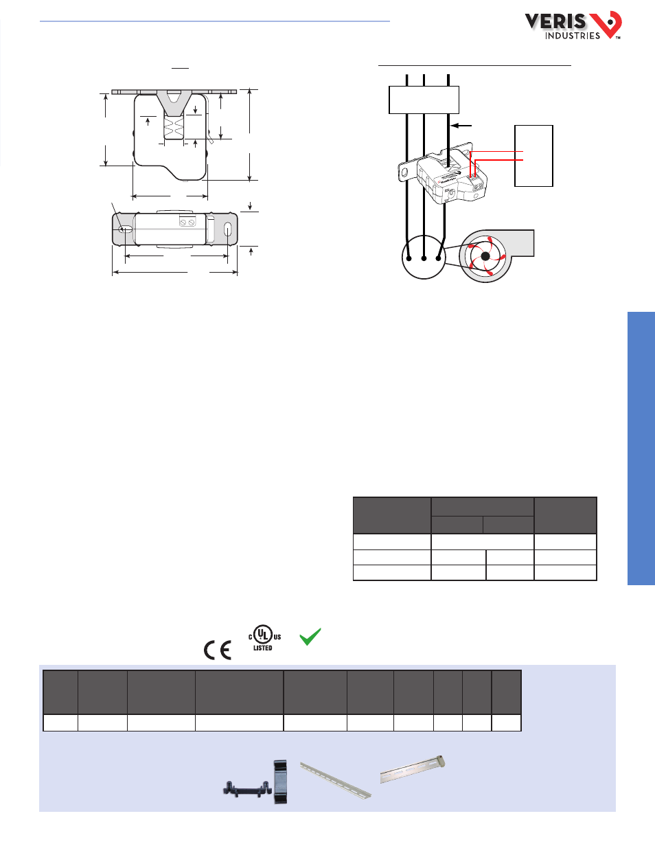
DIMENSIONAL DRAWING
*For best performance, monitor 5A or more current. At currents less than 5A, these ranges are approximate.
H10F
RoHS
Compliant
ALARM MODE
●
The ALARM state signals low current, high current, or power loss conditions
●
Initiated within 1 second when any load current excursion exceeds a nominal
±20%
●
ALARM will persist until the load current returns to within a nominal ±15% of
the learned current value, or when power is restored to normal
●
The 5% ALARM-to-NORMAL MODE reentry margin prevents alarm signal
oscillations. This feature is enhanced by a 30 second delay, to insure true
nominal load current conditions when returning to NORMAL MODE from an
ALARM state
●
The green LED shuts off, and the red LED blinks
●
STATUS OUTPUT contacts are open
OPERATING MODES
STATUS LEDS
STATUS
OUTPUT
GREEN
RED
LEARN (30 secs)
Alternating Blink On/Off
Contacts Closed
NORMAL
Blink
Off
Contacts Closed
ALARM*
Off
Blink
Contacts Open
* 1 sec maximum after detection.
1
Listed for use on 75°C insulated conductors.
APPLICATION/WIRING DIAGRAM
* Terminal block may extend up to 1/8” over the height dimensions shown.
ORDERING INFORMATION
Monitoring Fan /Pump Motors for Positive Proof of Flow
2.5" *
(64 mm)
2.1"
(54 mm)
3.5"
(89 mm)
2.9"
(74 mm)
0.4” x 0.2”
(10 mm x 5 mm)
Slot (2x)
1.2"
(31 mm)
Removable Mounting Bracket
0.7"
(18 mm)
0.5"
(13 mm)
2.1"
(54 mm)
1.0" *
(26 mm)
0.6"
(16 mm)
Motor
Pump or Fan
DDC CONTROLLER
Insulated
conductor
only
DI
CONTACTOR
ACCESSORIES
DIN Rail Clip Set (AH01)
DIN Rail (AV01) and DIN Stop Clip (AV02)
AH01
AV01
AV02
E150462
HQ0001757.B 01131