Current monit oring, Dimensional drawings ordering information, Application/ wiring diagram – Veris Industries Hx06 SERIES Datasheet User Manual
Page 2: Accessories, Rohs
current monit
oring
800.354.8556
+1 503.598.4564
www.veris.com
MODEL AMPERAGE
RANGE
STATUS OUTPUT
(max.)
MIN. TRIP
POINT
HOUSING STATUS LED
UL
CE
RoHS
H606
1.25 - 50A
N.C. 0.1A@30VDC
1.25A or less
Split-Core
n
n
1
n
n
H706
1-135A
1.0A or less
Solid-Core
n
n
n
H806
0.75 - 50A
0.75A or less
Solid-Core
n
n
n
n
H906
2.5-135A
2.5A or less
Split-Core
n
n
n
H606
H806
H906
H706
1
Listed for use on 75°C insulated conductors.
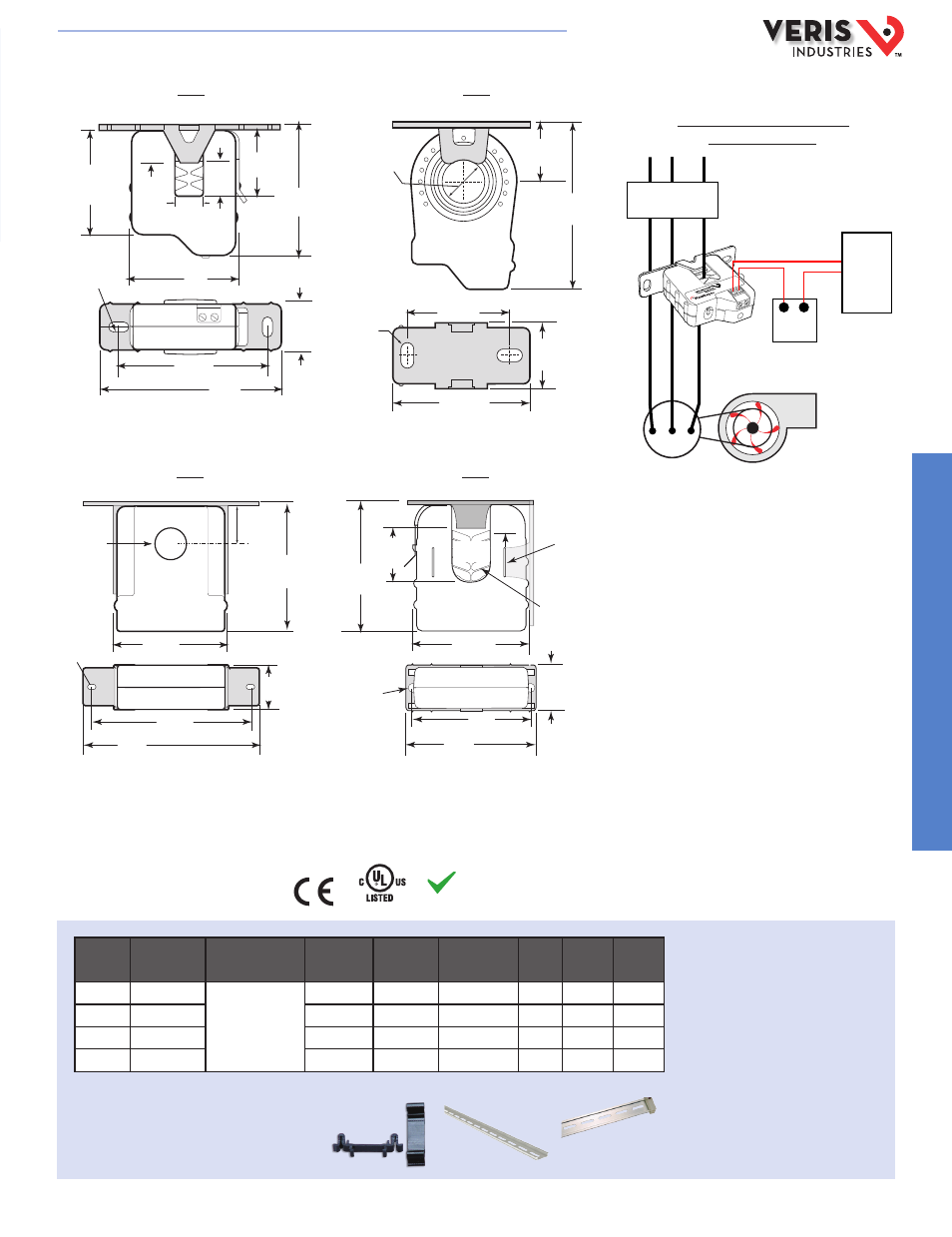
DIMENSIONAL DRAWINGS
ORDERING INFORMATION
Monitoring Fan /Pump Motors for
Positive Proof of Flow
* Terminal block may extend up to 1/8” over the height dimensions shown.
2.5" *
(64 mm)
2.1"
(54 mm)
3.5"
(89 mm)
2.9"
(74 mm)
0.4” x 0.2”
(10 mm x 5 mm)
Slot (2x)
1.2"
(31 mm)
Removable Mounting Bracket
0.7"
(18 mm)
0.5"
(13 mm)
2.1"
(54 mm)
1.0" *
(26 mm)
0.6"
(16 mm)
0 0.7"
(18 mm)
0.4” x 0.2”
Slot (x2)
2.8" *
(71 mm)
1.7
(43 mm)
2.3"
(58 mm)
1.1" *
(27 mm)
0.9"
(23 mm)
Removable/Adjustable Mounting Bracket
Removable Mounting Bracket
Self-gripping Iris
1.0”
(25 mm)
0.8”
(21 mm)
1.1”
(26 mm)
**3.1”
(79 mm)
2.8”
(70 mm)
Ø 0.3”
(8 mm)
1.4”*
(36 mm)
2.5”
(64 mm)
3.0”
(76 mm)
Bracket can
be mounted
on three sides
for added
installation
flexibility.
0.2” x 0.15”
slot (2x)
1.1" *
(27 mm)
2.8"
(68 mm)
0 0.7"
(19 mm)
0.9"
(23 mm)
3.0" **
(75 mm)
Removable/Adjustable Mounting Bracket
3.8"
(95 mm)
4.2"
(106 mm)
APPLICATION/
WIRING DIAGRAM
Motor
Fan or Pump
DDC CONTROLLER
DI
-
+
CONTACTOR
-
5-30VDC
POWER SOURCE
+
-
+
ACCESSORIES
DIN Rail Clip Set (AH01)
DIN Rail (AV01) and DIN Stop Clip (AV02)
AH01
AV01
AV02
RoHS
Compliant
E150462
HQ0001756.B 01131