Installation guide, Product overview, Wiring diagram – Veris Industries G SERIES Install User Manual
Page 2: Troubleshooting, Service, G series
Z202025-0P
PAGE 2
©2013 Veris Industries USA 800.354.8556 or +1(0)503.598.4564 / [email protected]
03131
Alta Labs, Enercept, Enspector, Hawkeye, Trustat, Aerospond, Veris, and the Veris ‘V’ logo are trademarks or registered trademarks of Veris Industries, L.L.C. in the USA and/or other countries.
TM
G SERIES
INSTALLATION GUIDE
PRODUCT OVERVIEW
The G Series carbon monoxide detectors measure CO levels and signal control systems
to provide an inlet of fresh air optimal for the space at a given time. G Series devices
are equipped with a relay contact that closes when the CO level is below 25 ppm
and opens when the CO level is above 25 ppm (when used with a normally closed
contactor). Removal of the sensor, interruption of power, or cut wires cause the relay
circuit to open and start the fan. Minimum relay cycle time is 3 minutes to prevent
fan short-cycling.
Audible Alarm: An 85 dB alarm sounds if the CO level rises above 100 ppm for 30
minutes.
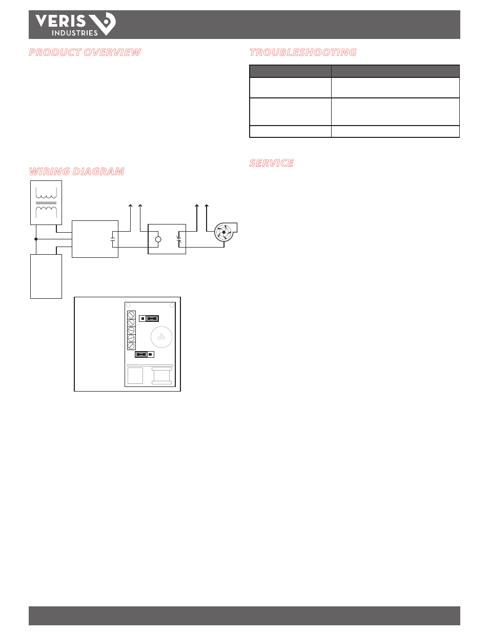
WIRING DIAGRAM
-
+
-
+
0-10V/0-5V
or
4-20mA
DDC
SYSTEM
V in
COMM
SENSOR
CONTACTOR
POWER
FAN
POWER
N.C.
CONTACTOR
ALARM
N.O.
OUT
SENSOR DETAIL
Common
Out 0-5V/10V or 4-20mA
IN V+ 15-30VDC, 24VAC
N.O. Relay
N.O. Relay
OUTPUT
10V
5V
PPM
100
200
TROUBLESHOOTING
Problem
Solution
4-20 mA output does not function • Verify that the unit is a 4-20 model.
• Verify that the unit is wired for sourcing output.
Output is half or twice what is
expected
• Verify span jumper is set to desired scale.
• For voltage units, verify jumper is set to desired
voltage output scale.
Output is inaccurate or unstable
• Allow 96 hours for sensor to burn in and stabilize.
SERVICE
For any service or installation, consult qualified service personnel. To ensure
continued reliable operation, replace the sensor module every five years with a Veris
Industries CO sensor replacement module (Veris part number AA09).
Replacement instructions:
1. Disconnect power from the unit.
2. Carefully remove the old sensor module.
3. Install the new module firmly into the socket.
4. Reconnect power to the unit.
5. The replacement sensor requires 96 hours to stabilize after initial power
application.
The sensor module is factory calibrated. No field calibration is required or possible.
Verify proper operation by observing the LED indicators.