Veris Industries G SERIES Install User Manual
G series, Notice, Carbon monoxide transmitter and fan controller
Z202025-0P
PAGE 1
©2013 Veris Industries USA 800.354.8556 or +1(0)503.598.4564 / [email protected]
03131
Alta Labs, Enercept, Enspector, Hawkeye, Trustat, Aerospond, Veris, and the Veris ‘V’ logo are trademarks or registered trademarks of Veris Industries, L.L.C. in the USA and/or other countries.
TM
ENVIRONMENTAL SENSORS
INSTALLATION GUIDE
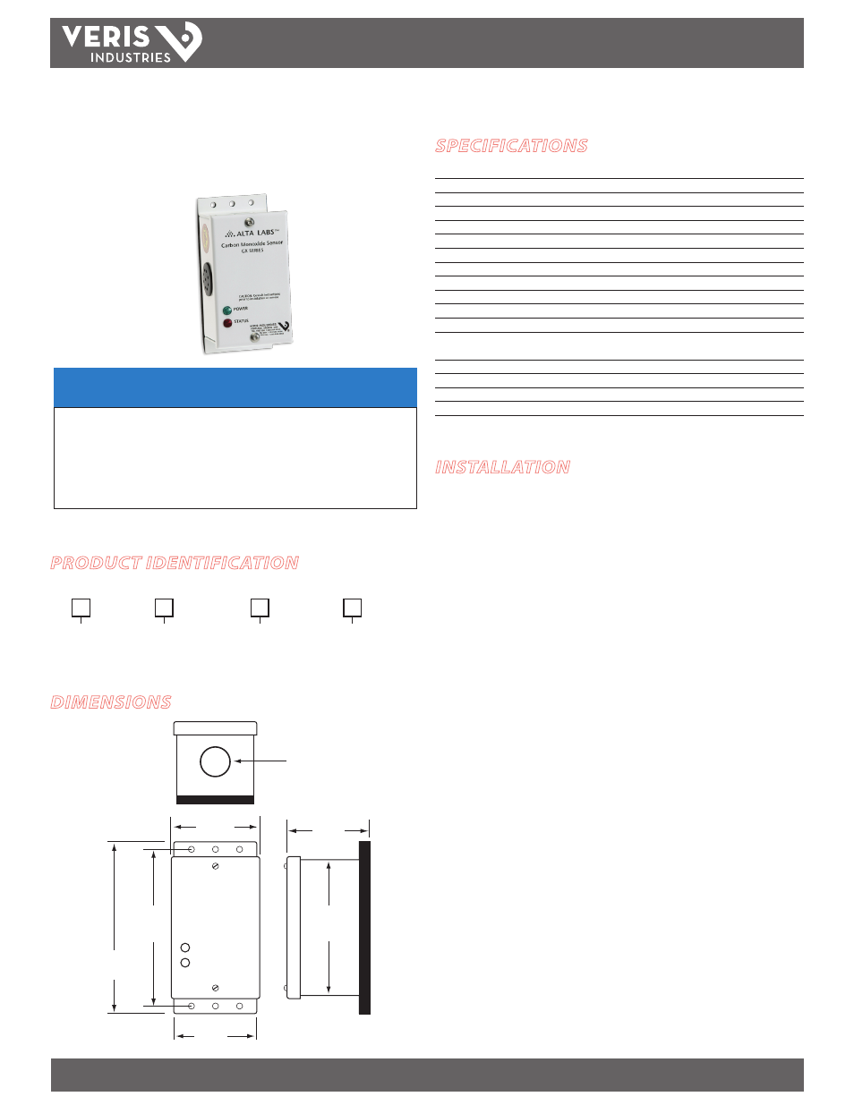
Carbon Monoxide Transmitter
and Fan Controller
SPECIFICATIONS
Input Power
15-30VDC/24VAC, 0.3A@24VAC
Sensor Type
Digitally profiled Metal Oxide Semiconductor (MOS)
Sensor Life
5-10 years typical, replaceable
Detection Range
0 to 200 ppm
Analog Output
3-wire sourcing, 4-20mA or user selectable 0-5V/0-10V (specify mA or V)
Output Scaling
User-selectable 100 ppm F.S. or 200 ppm F.S.
Response Time
2 min 30 sec sample interval cycle
Relay Output
N.O. Form A (SPST) 8A@30VAC/VDC; (Use with N.C. contactor)
Relay Setpoint
25 ppm
High Limit Setpoint
100 ppm for 30 minutes
High Limit Alarm Audible, 85 dB, resets below 100 ppm (solid-state contact for -AS version)
High Limit Contact (-AS Models)
250VAC/DC, 120mA max. Ron 35 Ω
LED Indicators
Solid Green = Normal; Solid Red = Call for ventilation;
Flashing
Green = Sensor life has expired; Flashing Red = High-limit alarm
Operating Temperature Range
-20° to 50°C (-4° to 122°F)
Operating Humidity Range
0 to 90% RH non-condensing
Coverage
5000 sq ft typical (465 sq m)
Housing
White powder coat over steel
G SerieS
DIMENSIONS
NOTICE
• This product is not intended for life or safety applications.
• Do not install this product in hazardous or classified locations.
• Read and understand the instructions before installing
this product.
• Turn off all power supplying equipment before working on it.
• The installer is responsible for conformance to all applicable codes.
No responsibility is assumed by Veris Industries for any consequences arising out of the
use of this material.
PRODUCT IDENTIFICATION
INSTALLATION
1. Lock out all power supplies prior to installation.
2. Select a location for the sensor in a secure area where it will be accessible only
to qualified service personnel. Install the G Series sensor centrally in the parking
structure, near the main traffic paths, but away from outside air vents and
excessive drafts. Mount the unit securely to a wall or column at a height of about 5
ft. (1.52 m) from the floor.
3. Connect wiring as shown in the Wiring section. If using a voltage output model,
use the Output jumper to select 0-5 V or 0-10 V.
4. Apply power to the unit. A green LED on the circuit board indicates proper
operation of the power supply.
Coverage is not dependent on the sensor. Coverage is a function of the building structure and air
flow patterns. A minimum of one sensor for 5000 sq. ft. is recommended. Wide open areas where
the air is well mixed may require multiple sensors.
2.4"
(55 mm)
2.5"
(63 mm)
0.9" dia.
(22 mm)
4.5”
(114 mm)
4"
(102 mm)
5.0"
(127 mm)
2.25"
(57 mm)
G
D = Duct mount
W = Wall mount
Enclosure
Auxiliary Alarm Output
Output
A = Auxiliary Contact
X = None
= Standard
V = Field-selectable,
0-5/0-10VDC
M =4-20mA
R = Relay only
S
US or EU