Installation guide, Wiring example, Setting contact jumper – Veris Industries H535 Install User Manual
Page 3
Z202808-0E
PAGE 3
©2012 Veris Industries USA 800.354.8556 or +1.503.598.4564 / [email protected]
07121
Alta Labs, Enercept, Enspector, Hawkeye, Trustat, Veris, and the Veris ‘V’ logo are trademarks or registered trademarks of Veris Industries, L.L.C. in the USA and/or other countries.
TM
INSTALLATION GUIDE
H535
d.) nipple mount to another enclosure:
Insert the conduit nuts (provided) into the slots in the side hole of the device
for additional weight support.
Connect line voltage wires
to line current terminals
ENCLOSURE
Nipple to existing enclosure
(conduit nipple fitting not provided)
Line voltage wires
Wire the 12 AWG lines from the controller through the side of the device,
from the enclosure to the line current terminals. Tighten line current terminal
blocks to 12 in-lb. (1.35 N-m) torque.
5. Use the knockout seal to cover any unused holes in the housing. Attach the cover,
securing with the screws provided.
NOTE: If a conduit is used, connect the conduit to the mounting hub before connecting it to the
device. Be sure to support the H535 housing when nipple-mounted to another enclosure, or the
unit may shift on opening, potentially causing undue stress on the wiring and the terminals.
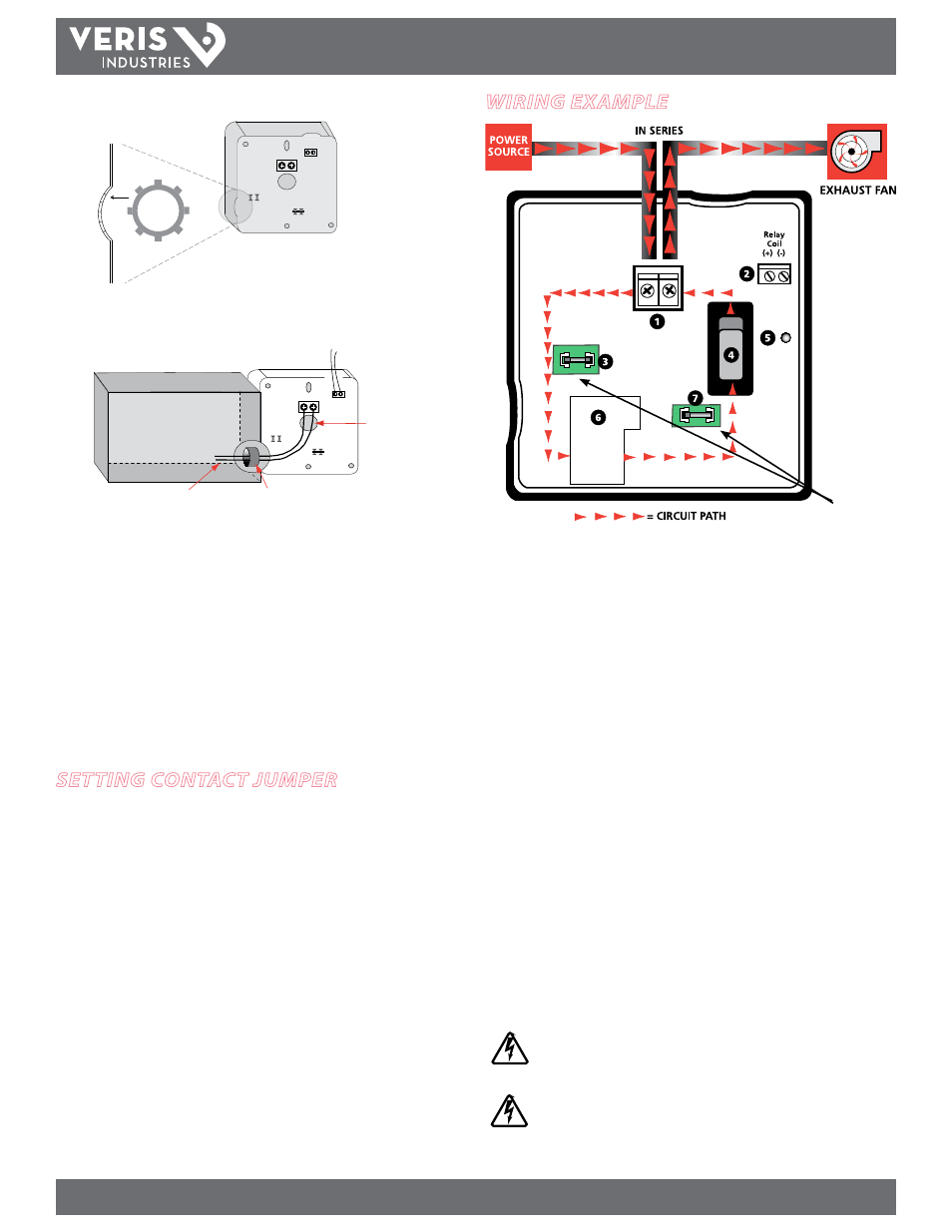
Wiring example
Keep all wires away
from the jumper block
areas.
1.
Relay Contacts:
Wire the H535 in series with the load using these terminals.
2.
Relay Coil Terminal Blocks:
Wire the output signal from the control panel to
actuate the relay. 24 VAC/DC; 36mA nominal
3.
N.C. Relay Jumper Block:
Insert a jumper here to ensure normally closed relay
operation when the switch is in auto position. Disconnect power to the device
before before touching the jumper.
4.
H.O.A. Switch:
Control the motor locally.
HAND – When the switch is in this position, the motor is always on.
OFF – When the switch is in this position, the motor is always off.
AUTO – When the switch is in this position, the control system commands the
motor.
5.
Relay Status LED:
For positive indication of energized coil.
6.
Relay:
Enables actuation of a circuit by a control system.
7.
N.O. Relay Jumper Block:
Insert a jumper here to ensure normally open relay
operation when the switch is in auto. Disconnect power to the device before
before touching the jumper.
CAUTION!
Do not rely on status indicators to determine whether or not the relay contacts are
connected to a power source. Doing so may result in injury or death from electrical
shock.
If the connections to the unit are made through more than one metallic conduit, bond
the conduits to prevent the hazard of electric shock. A bonding plate is available (Veris
part AH10).
setting contact jumper
The H535 has a jumper for N.O. or N.C. relay function. The jumper affects the relay
contacts only when the HOA switch is in AUTO. The product is shipped with the
jumper in the N.O. position. To select N.C. function, move to the N.C. jumper block.
Always disconnect power to the device before before touching the jumper.