Veris Industries H535 Install User Manual
Notice, Danger, Enclosed relay
TM
CURRENT MONITORING
INSTALLATION GUIDE
Z202808-0E
PAGE 1
©2012 Veris Industries USA 800.354.8556 or +1.503.598.4564 / [email protected]
07121
Alta Labs, Enercept, Enspector, Hawkeye, Trustat, Veris, and the Veris ‘V’ logo are trademarks or registered trademarks of Veris Industries, L.L.C. in the USA and/or other countries.
Enclosed Relay
Installer’s Specifications
Sensor Power
Induced from the monitored conductor
Amperage Range
0.25 to 15 A
Frequency Range
50-60 Hz
Operating Temperature Range
-15° to 50°C (5° to 122°F)
Operating Humidity Range
0-95%, noncondensing
Wire to Relay Contacts
Use 12 AWG (3.3 mm2) wire or larger*
Relay Switching Capacity at 120 VAC
1 HP
Relay Output
SPST F.S. N.O. or N.C., 15 Amps
Relay Coil
24 VAC/DC; 36 mA nom.
Terminal Block Torque
Relay control terminals: 3.5 in-lb (0.4 N-m)
All
other terminals: 12 in-lb (1.35 N-m)
Agency Approvals
UL508, Installation Category III
* For current loads up to 10A, use 75°C rated wire insulation. For loads greater than 10A, use 90°C
rated wire insulation.
The product design provides for basic insulation only.
HAZARD OF ELECTRIC SHOCK, EXPLOSION, OR ARC FLASH
• Follow safe electrical work practices.
See NFPA 70E in the USA, or applicable local codes.
• This equipment must only be installed and serviced by qualified electrical personnel.
• Read, understand and follow the instructions before installing this product.
• Turn off all power supplying equipment before working on or inside the equipment.
• Use a properly rated voltage sensing device to confirm power is off.
DO NOT DEPEND ON THIS PRODUCT FOR VOLTAGE INDICATION
• Only install this product on insulated conductors.
Failure to follow these instructions will result in death or serious injury.
DANGER
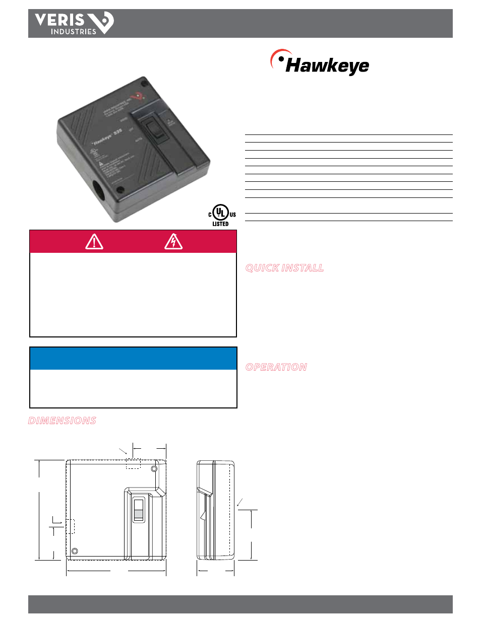
H535
535
Dimensions
NOTICE
• This product is not intended for life or safety applications.
• Do not install this product in hazardous or classified locations.
• The installer is responsible for conformance to all applicable codes.
• Mount this product inside a suitable fire and electrical enclosure.
2.13"
(55 mm)
1.16"
(30 mm)
4.25"
(108 mm)
1.53"
(39 mm)
C L
C L
C L
Wire
Opening
Wire
Opening
Wire
Opening
1.16"
(30 mm)
4.25"
(108 mm)
Quick install
1. Disconnect power sources prior to installation.
2. Remove the sensor lid and wire the command relay connections and relay controls
to the base.
3. Set the relay contact jumper.
4. This device has four wiring options, detailed on page 2-3 of this installation guide.
Choose the option appropriate to the application and follow instructions.
operation
The H535 combines a switching relay and a Hand-Off-Auto (HOA) switch in a single
housing. The H535 is connected in series between the power source and the motor
device. It operates at amperages up to a maximum of 15 A, and the relay and HOA
switch control the on/off functioning of the motor. The H535 requires no additional
power source for operation.
TM