Po wer/ener g y monit oring, Ordering information, Operation example – Veris Industries H704 SERIES Datasheet User Manual
Page 2: Network display (h8936), Model breaker spacing amperage range output, Other protocols available, consult factory
p
o
wer/ener
g
y monit
oring
800.354.8556
+1 503.598.4564
www.veris.com
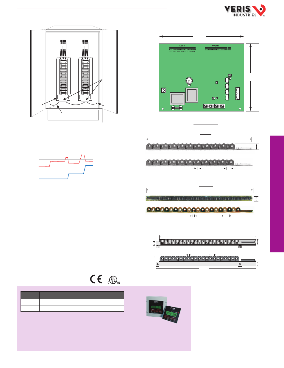
APPLICATION/WIRING EXAMPLES
DIMENSIONAL DRAWING
ACCESSORIES
Network Display (H8936)
ORDERING INFORMATION
HQ0001912.A 01121
MODEL
BREAKER SPACING
AMPERAGE RANGE
OUTPUT
H704-42
3/4” on center
10-50* (configurable)
RTU Modbus
†
H704-42/1
1” on center
10-50* (configurable)
RTU Modbus
†
For the 100A version, order the H704-42H or H704-42/1H.
For the 240VAC version, order the H704-42E or H704-42/1E.
For the 240VAC, 100A version, order the H704-42EH or H704-42/1EH.
For N2 protocol, order H726-xx.
Notes:
* Hole size accomodates up to 6 AWG (10mm2) THHN insulated conductors.
†
Other protocols available, consult factory.
LISTED
44XJ
IND:CONT EQ
6
4
2
12
10
8
18
16
14
24
22
20
30
28
26
36
34
32
42
40
38
7.25”
(184 mm)
5.75”
(146 mm)
19.5"
(241 mm)
0.75" on center
(19 mm)
0.35" opening
(9 mm)
1.0"
(26 mm)
24.0"
0.35" opening
1.0"
1.0" on center
19.5”
(495mm)
1.0”
(26mm)
0.75”
(19mm)
1.0”
(26mm)
0.4” opening
(10.16mm)
0.75” on center
(19mm)
1.2”
(31mm)
20.31”
(515mm)
Signal Acquisition Board
Current Sensor Strip
H704-42
H704-42/1
H704-xxH
H704-42 CURRENT SENSOR STRIP
H704-42 CURRENT SENSOR STRIP
H704-42 CURRENT SENSOR STRIP
H704-42 CURRENT SENSOR STRIP
H704-42
Data
Acquisition
Board
Modbus
Up to 63
H704-42s
Ribbon
Cable
To Controller
or PC
Panel Board 1
Panel Board 2
*20A
*Example represents 20 Amp circuit
†Configurable time delay for alarm and warning
0A
TIME
70% (14A)
Alarm Signal†
60% (12A)
Warning Signal†
Amp
Draw
E ect of
Rebalancing
Critical
State
Ckt. 1
Ckt. 2
OPERATION EXAMPLE