Veris Industries H722LC Install User Manual
Notice, Danger, Solid-core current transducer, 0-5vdc output
VERIS INDUSTRIES
™
CURRENT MONITORING
INSTALLATION GUIDE
Z202943-0A
PAGE 1
©2008 Veris Industries USA 800.354.8556 or +1(0)503.598.4564 / [email protected]
09083
Alta Labs, Enercept, Enspector, Hawkeye, Trustat, Veris, and the Veris ‘V’ logo are trademarks or registered trademarks of Veris Industries, L.L.C. in the USA and/or other countries.
Solid-Core Current Transducer,
0-5VDC Output
Installer’s Specifications
Amperage Range
0-10/20/40 Amps (slide switch selectable)
Sensor Power
Induced from monitored conductor
Insulation Class
600VAC RMS (UL), 300VAC RMS (CE)
Frequency
50/60Hz
Temperature Range
-15° to 60°C (5° to 140°F)
Humidity Range
10-90% RH, non-condensing
Accuracy
±2% FS from 10% - 100% of selected range
Response Time
2 sec.
Terminal Block Maximum Wire Size
14 AWG
Terminal Block Torque (nominal)
4 in-lbs (0.45 N-m)
Agency Approvals
UL 508 open device listing
CE: EN61010-1:2001-2, CAT III, deg. 2, basic insulation
HAZARD OF ELECTRIC SHOCK, EXPLOSION, OR ARC FLASH
• Follow safe electrical work practices.
See NFPA 70E in the USA, or applicable local codes.
• This equipment must only be installed and serviced by qualified electrical personnel.
• Read, understand and follow the instructions before installing this product.
• Turn off all power supplying equipment before working on or inside the equipment.
• Use a properly rated voltage sensing device to confirm power is off.
DO NOT DEPEND ON THIS PRODUCT FOR VOLTAGE INDICATION
• Only install this product on insulated conductors.
Failure to follow these instructions will result in death or serious injury.
DANGER
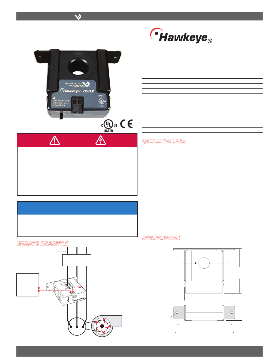
Wiring ExamplE
H722LC
722LC
DimEnsions
NOTICE
• This product is not intended for life or safety applications.
• Do not install this product in hazardous or classified locations.
• The installer is responsible for conformance to all applicable codes.
• Mount this product inside a suitable fire and electrical enclosure.
quick install
Disconnect and lock out power.
1.
Install the mounting bracket to the back of the electrical enclosure, no closer than
2.
1/2” (12mm) to an uninsulated conductor.
Slide the conductor to be monitored through the sensing hole of the current
3.
switch. Terminate the conductor. See Notes (page 2) for currents under 1 Amp or
above 40 Amp.
Set the desired amperage range on the H722LC (10, 20, or 40 Amps).
4.
Wire the output connections between the H722LC and the controller (0-5VDC).
5.
Reconnect power.
6.
Scale the controller software to match the H722LC’s output.
7.
0.2” x 0.15”
slot (2x)
1.1"
(27 mm)
2.8"
(68 mm)
0.7" Dia
(19 mm)
0.9"
(23 mm)
3.0"
(75 mm)
Removable/Adjustable Mounting Bracket
3.8"
(95 mm)
4.2"
(106 mm)
Fan or Pump
CONTROLLER
0-5VDC
COMM
+
–
AI
VERIS INDUSTRI
ES
Portland, Ore
gon 97223
1-800-354-85
56
CONTACTOR
Insulated Conductor Only