Veris Industries SD QUICK START GUIDE User Manual
Quick start guide
S D S D - Z S D - R O 1
QUICK START GUIDE
S D s e r
i
e s
SD – Spot Detector
1. Installation
Determine a location. Ram set 6/32 threaded studs in floor on 2.5 inch (63.5mm) centers. Place SD over studs and
secure. Adjust the sense probes to desired height. Connect the white/red and black leads to the FMS, F-Series or
LDRA6 panel. A 24VAC power supply is required for use with a Falcon RA1x2. Test the SD by placing water
under the sense probes.
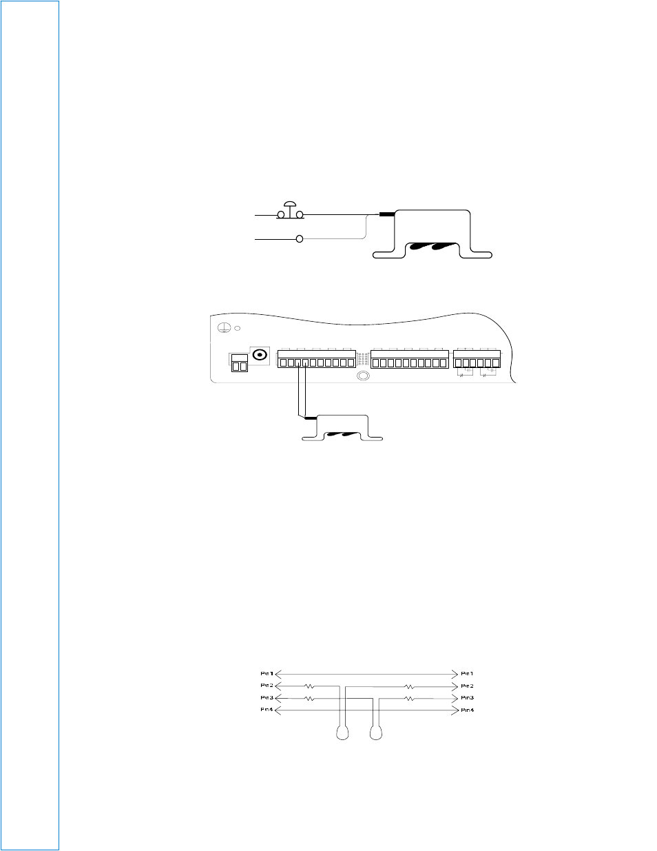
SD Diagram 1
SD Diagram 2: Falcon Wiring
SD-Z – Zone Spot Detector
1. Installation
Determine a location. Ram set 6/32 threaded studs in floor on 2.5 inch (63.5mm) centers. Place SD-Z over studs
and secure. Adjust the sense probes to desired height. Connect the SD-Z to the LDZ control panel by connecting
the two cable connectors to SeaHawk Water Leak Detection Cable (SC), or SeaHawk Non-Sensing Cable (NSC), or
an end terminator (EOL) as shown in SD-Z Diagram 2. Test the SD-Z by placing water under the sense probes.
SD-Z simulates 50 feet (15.24m) of SC cable: 25 feet in and 25 feet out (7.62m in/out) from device.
SD-Z Diagram 1: Pins
P 1
V D C
T B 1
V D C
+ -
E X T E R N A L
2 4 V D C
+ +
C h 1
+ -
C h 2
+ -
C h 3
+ -
C h 4
+ -
T B 2 In p u t 1 -4
C h 5
+ -
C h 6
+ -
C h 7
+ -
T B 3 In p u t 5 -8
C h 8
+ -
E X T E R N A L
G N D
- -
T B 4
N C N O C
R E L A Y 1
N C N O C
R E L A Y 2
Wh
ite
/Re
d
Bl
ac
k
White/Red (+)
Black (-)
NC Reset
Push Button
24 VDC
(
Polarity is
Not important
)
Once triggered, latches on, until
power is removed (VDC)