Installation guide, Wiring, Output scaling – Veris Industries CWV SERIES Install User Manual
Page 2: Calibration process, Configuration, Led indication, Cwv series, Step 1 calibration port
Z204905-0F
PAGE 2
©2013 Veris Industries USA 800.354.8556 or +1.503.598.4564 / [email protected]
03131
Alta Labs, Enercept, Enspector, Hawkeye, Trustat, Aerospond, Veris, and the Veris ‘V’ logo are trademarks or registered trademarks of Veris Industries, L.L.C. in the USA and/or other countries.
TM
CWV SERIES
INSTALLATION GUIDE
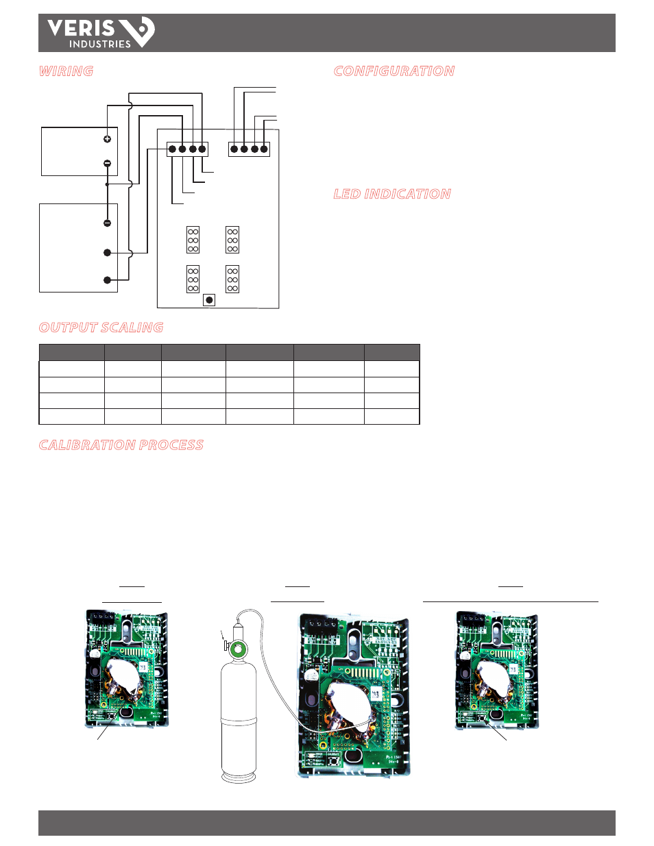
WIRING
POWER SOURCE
20 to 30 VDC
or
24 VAC
COMMON
Output #2 mA or voltage
Power
Ground
Output #1 mA or voltage
INPUT mA OR VOLTAGE
INPUT mA OR VOLTAGE
DDC PANEL
V OUT 1
Relay 2
V OUT 2
Relay 1
10
5
3
Status
800
1000
Status
800
1000
10
5
3
Relay 2/temp
output (optional)
Relay 1 output
(optional)
Calibrate
OUTPUT SCALING
CO2 PPM
0-3 Volt Output
0-5 Volt Output
0-10 Volt Output
mA Output
Outside
300-500
0.45 to 0.75
0.75 to 1.25
1.5 to 2.5
6.4 to 8
Over Ventilated
Under 600
Under 0.9
Under 1.5
Under 3
Under 8.8
Ideal Ventilation
600-900
0.9 to 1.35
1.5 to 2.25
3 to 4.5
8.8 to 11.2
Under Ventilated
Over 900
Over 1.35
Over 2.25
Over 4.5
Over 11.2
CALIBRATION PROCESS
1. Remove the cover and connect a hose to the plastic port located on the sensing
module.
2. Begin nitrogen gas flow (0 ppm CO2). Use a flow rate of 0.3 to 0.5 liter/minute,
using the Veris AA01 Calibration Kit or equivalent.
3. Push and hold down the calibration button for 8 seconds.
4. Release the calibration button and verify that the analog outputs are at either 4
mA or 0 V. If the outputs are not showing these values, repeat steps 3 and 4.
STEP 1
Calibration Port
Connect hose here
STEP 2
Flow Nitrogen
STEP 3
Push and hold calibration button for 8 seconds
Calibration button
CONFIGURATION
1. If so equipped, select the voltage outputs by jumpering the V Out 1 and/or V Out 2,
as indicated at left (10=0-10VDC, 5=0-5VDC, 3=0-3VDC).
2. If so equipped, select the relay mode by jumpering the Relay 1 and/or Relay 2
function blocks, as indicated at left (Status=sensor condition, 800=800ppm CO2
setpoint, 1000=1000ppm CO2 setpoint).
Veris AA01 Calibration Kit
(or equivalent)
Note: Do not breathe on the CO2 sensor
during the calibration process.
NITROGEN
GAS
Regulator
Valve
LED INDICATION
Green - Power applied to device
Red - Error condition for false reading, CO2 concentration > 10,000 ppm, insufficient
power, or improperly calibrated sensor.
The red LED briefly illuminates for approximately two seconds when the CWV device
is initially powered. It then deluminates, indicating normal sensor operation.