Veris Industries CWV SERIES Install User Manual
Cwv series, Notice, Environmental co
Z204905-0F
PAGE 1
©2013 Veris Industries USA 800.354.8556 or +1.503.598.4564 / [email protected]
03131
Alta Labs, Enercept, Enspector, Hawkeye, Trustat, Aerospond, Veris, and the Veris ‘V’ logo are trademarks or registered trademarks of Veris Industries, L.L.C. in the USA and/or other countries.
TM
ENVIRONMENTAL SENSORS
INSTALLATION GUIDE
Environmental CO
2
Sensors
SPECIFICATIONS
Input Voltage
20 to 30VDC, 24VAC
Analog Output #1
4-20mA (clipped & capped) or 0-3VDC/0-5VDC/0-10VDC
(jumper
selectable)
Analog Output #2
4-20mA (clipped & capped) or 0-3VDC/0-5VDC/0-10VDC
(jumper
selectable)
Sensor Current Draw
200mA Maximum
Operating Humidity Range
0-95% RH (noncondensing)
Operating Temperature Range
0° to 50°C (32° to 122°F)
Housing Material
High impact ABS plastic
Relay Contacts (optional)
Form C (SPDT) 1A@30VDC, resistive; 30W max.
CO2 Transmitter:
Sensor Type
Non-dispersive infrared (NDIR), diffusion sampling
Measurement Range
0-2000 ppm
Accuracy
±40 ppm ±8.5% of measured value
Repeatability
±30 ppm ±4.5% of measured value
Response Time
<60 seconds for 90% step change
EMC Conformance: EN 61000-6-3:2007+A1:2011 Class B, EN 61000-6-1:2007
EMC Special Note: Connect this product to a DC distribution network or an AC/DC power adaptor
with proper surge protection (EN 61000-6-1:2007 specification requirements).
RTD/Thermistors are not compensated for internal heating of product.
CWV SerieS
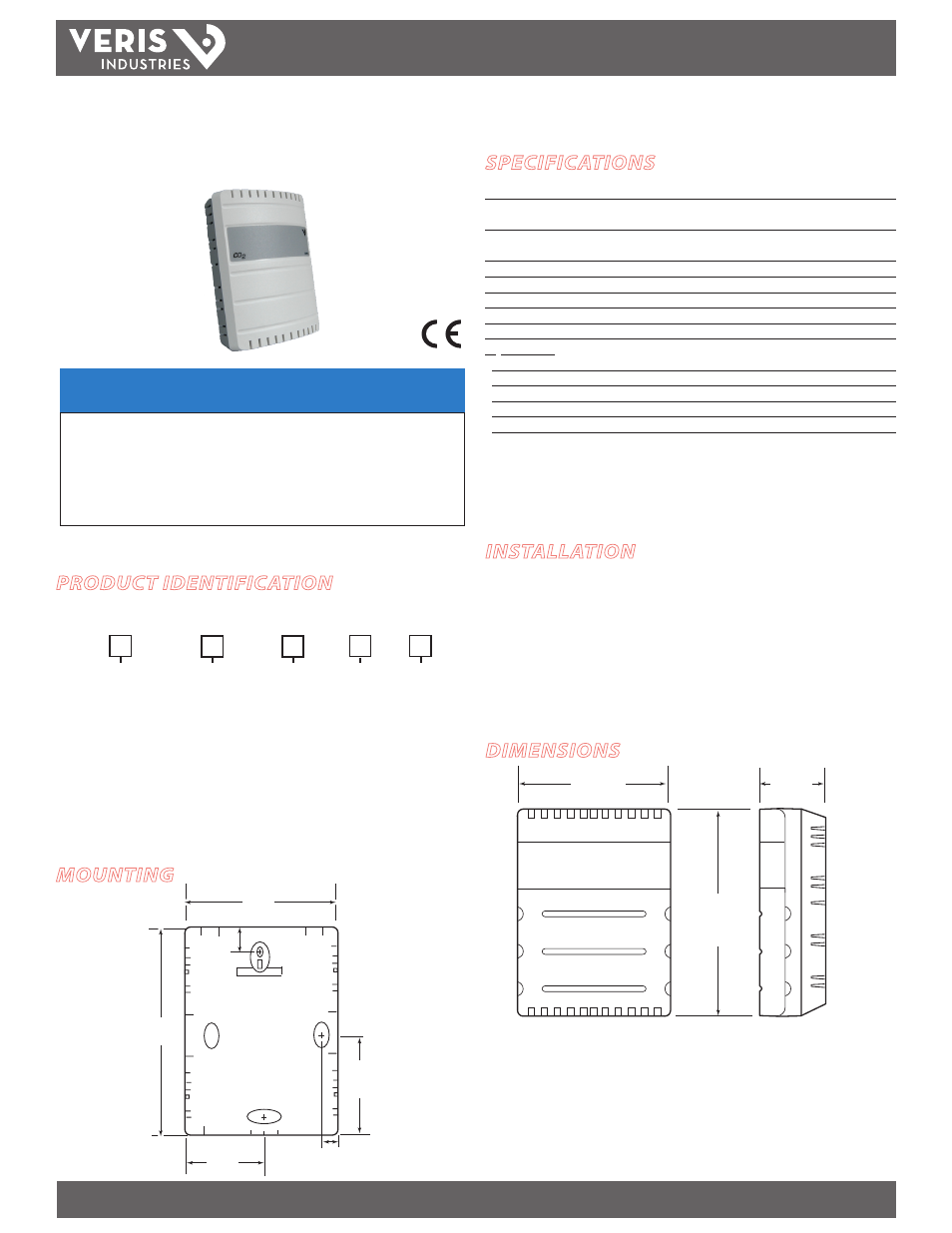
DIMENSIONS
NOTICE
• This product is not intended for life or safety applications.
• Do not install this product in hazardous or classified locations.
• Read and understand the instructions before installing
this product.
• Turn off all power supplying equipment before working on it.
• The installer is responsible for conformance to all applicable codes.
No responsibility is assumed by Veris Industries for any consequences arising out of the
use of this material.
PRODUCT IDENTIFICATION
INSTALLATION
1. Select a mounting location with good air circulation. For room installations, mount
the sensor 4 ½ feet (1.4 m) above the floor.
2. Remove the cover. Flush mount the CWV on a wall or on a standard US or European
single gang junction box.
3. Wire the device. Refer to the wiring diagram.
4. Install the cover.
MOUNTING
4.6"
(116 mm)
3.3"
(84 mm)
1.4"
(36 mm)
.64”
(16 mm)
.46"
(12 mm)
4.6"
(116 mm)
2.2"
(54 mm)
1.6"
(42 mm)
3.3"
(84 mm)
CWVS
Output
Warranty
1 = 0-3/5/10VDC
and 4-20mA
2 = 4-20mA and
4-20mA
3 = 0-3/5/10VDC
and 0-3/5/10VDC
1 = 1 year
3 = 3 years
5 = 5 years
Housing
Relay option
Blank = White/
gray
B = Black
Temp/2nd
Relay option
X = No temp.
1 = Relay
B = 100R Pt
C = 1k Pt
D = 10k T2
E = 2.2k
F = 3k
H = 10k T3
J = 10k Dale
K = 10k with 11kS
M = 20k NTC
N = 1800 ohm
R = 10K US
S = 10K 3A1B
X = No relay
1 = Relay