Air qu alit y, Dimensional drawing application/wiring diagram, Accessories – Veris Industries CWV SERIES Datasheet User Manual
Page 2: Ordering information
AIR QU
ALIT
Y
800.354.8556
+1 503.598.4564
www.veris.com
CWVS
Outputs
Relay Option
1 = 0-3/5/10VDC and 4-20mA
2 = Dual 4-20mA
3 = Dual 0-3/5/10VDC
X = None
1 = Relay
Warranty
1 = 1 Year
3 = 3 Years
5 = 5 Years
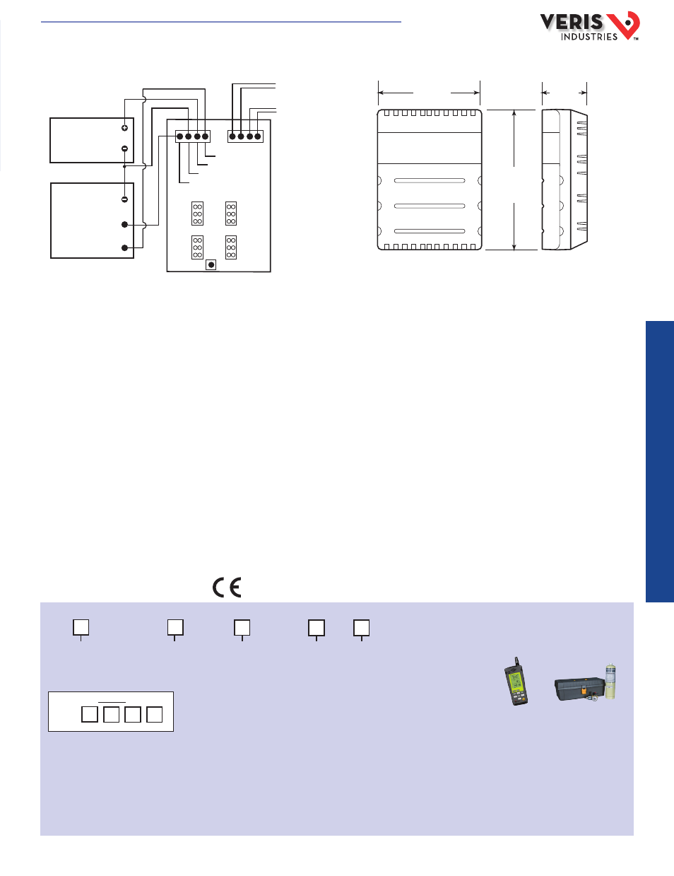
DIMENSIONAL DRAWING
APPLICATION/WIRING DIAGRAM
Thermistor/2nd Relay option
X = No option
B = 100R Platinum
C = 1k Platinum
D = 10k T2
E = 2.2k
F = 3k
H = 10k T3
J = 10k Dale
K = 10k w/11k with shunt
M = 20k NTC
N = 1800 ohm
P = 10m V/C
R = 10k US
S = 10k 3A 221
U = 20k “D”, Thermistor
W = 10k T2 high accuracy, Thermistor
Y = 10k T3 high accuracy, Thermistor
Z = 10k E1, Thermistor
1 = Relay
Example:
ACCESSORIES
Calibration kits and gases (AA01, AA26, AA27,
AA28, AA29)
Handheld air quality testers (1010, 1008, 770)
Housing
Blank = White/gray
B = Black
ORDERING INFORMATION
CWVS
1
1
1 5
POWER SOURCE
20 to 30 VDC
or
24 VAC
COMMON
Output #2 mA or voltage
Power
Ground
Output #1 mA or voltage
INPUT mA OR VOLTAGE
INPUT mA OR VOLTAGE
DDC PANEL
V OUT 1
Relay 2
V OUT 2
Relay 1
10
5
3
Status
800
1000
Status
800
1000
10
5
3
Relay 2/temp
output
(optional)
Relay 1 output
(optional)
Calibrate
4.6"
(116 mm)
3.3"
(84 mm)
1.4"
(36 mm)
AA01
1010
HQ0001742.B 01131