Caution, Installation guide, Operation – Veris Industries H923 Install User Manual
Page 2: Scaling, Troubleshooting, Wiring, H923
H923
Z202365-0H
PAGE 2
©2012 Veris Industries USA 800.354.8556 or +1.503.598.4564 / [email protected]
04122
Alta Labs, Enercept, Enspector, Hawkeye, Trustat, Veris, and the Veris ‘V’ logo are trademarks or registered trademarks of Veris Industries, L.L.C. in the USA and/or other countries.
TM
INSTALLATION GUIDE
OPERATION
The H923 is a current transducer that senses current (amperage) in any of three
field-selectable ranges; 0-to-20, 0-to-100, or 0-to-150 Amps. These ranges represent
the maximum current that can be applied to the monitored conductor. The H923
transforms the monitored current into a 0 to 10 VDC output suitable for connection
to building controllers or other appropriate data acquisition equipment. The H923
requires no external power supply to generate its output.
The H923 housing offers unprecedented mounting flexibility. The mounting bracket
can be attached in three different places. Additionally, the bracket is compatible with
the Veris AH01 DIN Rail clip, allowing DIN mounting.
NOTES
For load currents greater than sensor maximum rating:
Use a 5 Amp (H68xx series) Current Transformer (CT) as shown. This technique can be
combined with wrapping (see below) to add range for a low current load on a high
current source.
For load currents less than sensor minimum rating:
Wrap the monitored conductor through the center window and around the sensor
body to produce multiple turns. This increases the current measured by the
transducer.
4x
1A
DANGER: 5A CTs can present hazardous voltages.
Install CTs in accordance with manufacturer's instructions.
Terminate the CT secondary before applying current.
H68xx-5A CT
240A
300A:
5A
4A
> 150A (Sensor max.)
CAUTION
RISK OF EQUIPMENT DAMAGE
• Derate the product’s maximum current for the number of turns
through the sensing window using the following formula.
Rated Max. Amps ÷ Number of Turns = Max. monitored Amps
e.g. : 100A ÷ 4 Turns = 25 Amps max. in monitored conductor
• Failure to follow these instructions can result in overheating
and permanent equipment damage.
Program the controller to
account for the extra turns,
e.g., if four turns pass through
the sensor (as shown) then
divide the normal controller
reading by 4.
< 1.5 A (Sensor Min.)
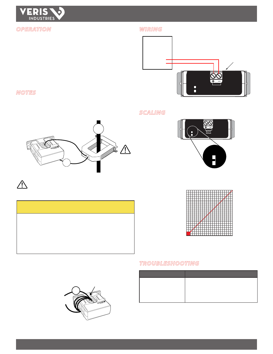
SCALING
1. Set range switch.
2. Scale controller
software to match
selected output.
20
100
150
Amperage Range
Selector Switch
20
100
150
AMPERAGE RANGE
AMPERAGE RANGE
SENSOR OUTPUT
Selected Range
0V
0A
10V
SENSED AMPS
TROUBLESHOOTING
Problem
Solution
No Reading at Controller
• Check polarity of sensor output connections
• Check for output voltage at sensor
• Check for amperage in monitored conductor
• Assure that sensor core mating surfaces are clean and
that the core clamp is completely closed
DDC
CONTROLLER
AI
COMM
0-10VDC Input +
–
Self-Powered Output
20
100
150
OUTPUT
0-10VDC
AMPERAGE RANGE
WIRING