Veris Industries H923 Install User Manual
H923, Notice, Danger
CURRENT MONITORING
Z202365-0H
PAGE 1
©2012 Veris Industries USA 800.354.8556 or +1.503.598.4564 / [email protected]
04122
Alta Labs, Enercept, Enspector, Hawkeye, Trustat, Veris, and the Veris ‘V’ logo are trademarks or registered trademarks of Veris Industries, L.L.C. in the USA and/or other countries.
TM
INSTALLATION GUIDE
Split-Core Current Transducer,
0-10VDC Output
Installer’s Specifications
Amperage Range
0-20/100/150A (slide-switch selectable)
Sensor Power
Induced from monitored current
Insulation Class
300VAC RMS
Frequency Range 50/60Hz
Temperature Range
-15° to 60°C (5° to 140°F)
Humidity Range
10 - 90% RH, non-condensing
Accuracy
±2% full scale from 10% to 100% (selected range)
Response Time
2 sec.
Terminal Block Maximum Wire Size
14 AWG
Terminal Block Torque (nominal)
4 in-lbs (0.45 N-m)
Agency Approvals
CE: EN61010-1:2001-2, CAT III, pollution degree 2, basic insulation
For applications requiring double or reinforced insulation, please contact the factory
HAZARD OF ELECTRIC SHOCK, EXPLOSION, OR ARC FLASH
• Follow safe electrical work practices.
See NFPA 70E in the USA, or applicable local codes.
• This equipment must only be installed and serviced by qualified electrical personnel.
• Read, understand and follow the instructions before installing this product.
• Turn off all power supplying equipment before working on or inside the equipment.
• Use a properly rated voltage sensing device to confirm power is off.
DO NOT DEPEND ON THIS PRODUCT FOR VOLTAGE INDICATION
• Only install this product on insulated conductors.
Failure to follow these instructions will result in death or serious injury.
DANGER
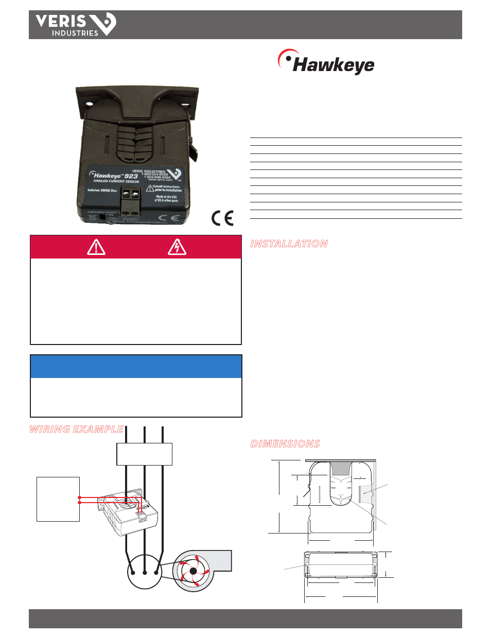
WIRING EXAMPLE
H923
TM
923
DIMENSIONS
NOTICE
• This product is not intended for life or safety applications.
• Do not install this product in hazardous or classified locations.
• The installer is responsible for conformance to all applicable codes.
• Mount this product inside a suitable fire and electrical enclosure.
Fan or Pump
CONTROLLER
0-10VDC
COMMON
–
+
AI
CONTACTOR
Removable Mounting Bracket
Self-gripping
Iris
1.0”
(25 mm)
0.8”
(21 mm)
1.1”
(26 mm)
3.1”
(79 mm)
2.8”
(70 mm)
Ø = 0.3”
(8 mm)
1.4”
(36 mm)
2.5”
(64 mm)
3.0”
(76 mm)
Bracket can be mounted
on three sides for added
installation flexibility.
Use DIN Rail
Mounting clip
(Veris part
number AH01) to
mount on stan-
dard DIN rail.
INSTALLATION
Disconnect and lock out power to the enclosure containing the
conductor to be monitored.
1. Locate a mounting surface for the removable mounting bracket that will allow
the monitored conductor to pass through the center window when it is installed
and that will keep the device at least 1/2” from any uninsulated conductors.
Determine cable routing for the controller connection, allowing wiring to reach
the mounting location.
2. Drill holes to mount the bracket to the chosen surface using the included screws.
3. Set the desired amperage range (20, 100, or 150 Amps).
4. Wire the output connections between the sensor and the controller (0-10VDC).
5. Snap the sensor over the conductor to be monitored and clip the assembly to the
mounting bracket.
6. Scale the controller software to match the sensor output.
7. Secure enclosure and reconnect power.