Le ak dete ction, Model manuf. part # description ce rohs etl – Veris Industries MX1 Datasheet User Manual
Page 2
LE
AK DETE
CTION
800.354.8556
+1 503.598.4564
www.veris.com
ORDERING INFORMATION
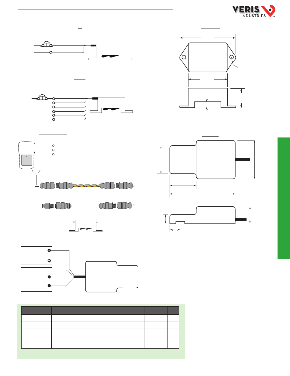
DIMENSIONAL DRAWINGS
APPLICATION/WIRING DIAGRAMS
SD thru SD-Z
MX1 Series
MX1 Series
SD-R01
SD
MODEL
MANUF. PART #
DESCRIPTION
CE
RoHS ETL
U006-0006
SD
Spot Detector, 14’ leader cable
U006-0007
SD-R01
Spot Detector, 14’ leader cable, relay out
U006-0008
SD-Z*
Spot Detector, 2x10” leader cable
MX1B
MX1B
Spot Detector, battery
MX1V
MX1V
Spot Detector, 12-30VDC/24VAC
SD-Z
The SD-Z works with all panels (LD300 and
LD1000 shown here; LD5100, LDRA6, and
LD2000 are also compatible).
24 VDC
(not polarity
sensitive)
(Normally Closed)
Reset Push Button
White/Red (+)
Black (-)
Once triggered, device remains on
until power is removed (if using VDC power).
24 VAC/DC
(Normally Closed,
VDC applications only)
Reset Push Button
Red (+)
Brown (Not Used)
Blue (N.C.)
Green (Comm)
White (N.O.)
Black (-)
Once triggered, device remains on
until power is removed (if using VDC power).
Power/Alarm
LD300
or
SC
NSC
End Terminator
(EOL)
Leader cable kit
(LC-Kit)
Spot detector
(SD-Z)
LD1000
POWER SOURCE
DIGITAL CONTROL
Digital Input
Black
Red
NOTE: Power supply not required
for battery powered version
White
Green
12 to 30VDC/24VAC
1.0”
(25 mm)
0.3” (8 mm)
0 = 0.2”
(5 mm)
2.1”
(52 mm)
2.9”
(73 mm)
0.3"
(7 mm)
0.3"
(7 mm)
0.6"
(14 mm)
0.75"
(19 mm)
1.75"
(44 mm)
1.2"
(30 mm)
0.5"
(13 mm)
* The SD-Z uses DIN style connectors. Connect it via the LC-KIT, or integrate it into an LC-KIT-SC/NSC cable configuration.
HQ0001797.B 01131