Te mpera ture, Application/wiring diagrams, Dimensional drawings – Veris Industries TE SERIES Datasheet User Manual
Page 2: Ordering information, Accessories
TE
MPERA
TURE
800.354.8556
+1 503.598.4564
www.veris.com
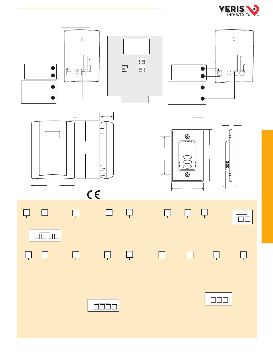
POWER SOURCE
12 to 30VDC/24VAC
DIGITAL CONTROL
Temperature
0-5/0-10V
-
--
+
Thermistor, RTD
or Override
Right
Wiper
Left
Setpoint
32° to 122°
50° to 95°
0° to 50°
10° to 35°
Temp Range
10V
5V
Voltage Range
°C
°F
Temp Scale
TW Series – 0-5/0-10V
POWER SOURCE
12 to 30VDC Only
DIGITAL CONTROL
Temperature
4-20mA
-
--
+
Thermistor, RTD
or Override
Right
Wiper
Left
Setpoint
NOTE: For 24VAC transformer
powered applications, one side of
transformer secondary is connected
to common. Isolation transformer,
or dedicated power supply may be
required.
TW Series – 4-20mA
APPLICATION/WIRING DIAGRAMS
TW
TE/TEA
Sensor Type
TW
Local Display
= Transmitter selectable
outputs
L = LCD
X = No
Setpoint/Override
Cal Certificate
0 = None
1 = 1 point
Cal validation
2 = 2 point
Cal validation
Example:
TW X A 0 2
Sensor Type
TW
Local Display
L = LCD
X = No
Setpoint/Override
Cal Certificate
0 = None
2 = 1k Setpoint
3 = 10k Setpoint
4 = 1k Setpoint w/override
5 = 10k Setpoint w/override
0 = None
1 = 1 point
Cal validation
2 = 2 point
Cal validation
Example:
TW L
C
0
1
*NOTE: Pushbutton override short circuits RTD/thermistor output
Output
US or EU
M = 4-20mA
V = 0-10VDC
J = 0-5VDC
= Standard
TEA
Example:
TEA J S
S
Sensor Type
Setpoint/Override
TE
B = 100R Platinum, RTD
C = 1k Platinum, RTD
D = 10k T2, Thermistor
E = 2.2k, Thermistor
F = 3k, Thermistor
G = 10k CPC, Thermistor
H = 10k T3, Thermistor
J = 10k Dale, Thermistor
K = 10k w/11k shunt,Thermistor
M = 20k NTC, Thermistor
N = 1800 ohm, Thermistor
P = 10mV/°C, Linitemp
R = 10k US, Thermistor
S = 10k 3A221, Thermistor
T = 100k, Thermistor
U = 20k “D”, Thermistor
W = 10k T2 high accuracy, Thermistor
Y = 10k T3 high accuracy, Thermistor
Z = 10k E1, Thermistor
0 = None
1 = Override
2 = 1k Setpoint
3 = 10k Setpoint
4 = 1k Setpoint w/override
5 = 10k Setpoint w/overrid
e
Cal Certificate
0 = None
1 = 1 point Cal validation
2 = 2 point Cal validation
DIMENSIONAL DRAWINGS
0 = None
1 = Override*
2 = 1k Setpoint
3 = 10k Setpoint
4 = 1k Setpoint w/override*
5 = 10k Setpoint w/override*
B = 100R platinum, RTD
C = 1k platinum, RTD
D = 10k T2, Thermistor
E = 2.2k, Thermistor
F = 3k, Thermistor
G = 10k CPC, Thermistor
H = 10k T3, Thermistor
J = 10k Dale, Thermistor
K = 10k w/11k shunt,Thermistor
M = 20k NTC, Thermistor
N = 1800 ohm, Thermistor
P = 10mV/°C, Linitemp
R = 10k US, Thermistor
S = 10k 3A221, Thermistor
T = 100k, Thermistor
U = 20k “D”, Thermistor
W = 10k T2 high accuracy, Thermistor
Y = 10k T3 high accuracy, Thermistor
Z = 10k E1, Thermistor
ORDERING INFORMATION
Housing Color
None = Cloud
White
B = Black
A
Housing Color
None = Cloud White
B = Black
Housing Color
None = Cloud White
B = Black
Example:
TE D 5 2
Housing Color
None = Cloud White
B = Black
ACCESSORIES
Replacement covers for wall units (AA51, AA51B,
AA52, AA52B)
Replacement cloud white wall housing (AA55)
4.5"
(115 mm)
0.25"
(6 mm)
0.5"
(13 mm)
2.8"
(72 mm)
3.2"
(82 mm)
1.2"
(31 mm)
3.5"
(89 mm)
4.8"
(122 mm)
HQ0001876.C 05131