Installation, Installation guide pressure pw series – Veris Industries PW SERIES Install User Manual
Page 3
Z202882-0U
Page 3 of 4
©2013 Veris Industries USA 800.354.8556 or +1.503.598.4564 / [email protected] 06131
Alta Labs, Enercept, Enspector, Hawkeye, Trustat, Aerospond, Veris, and the Veris ‘V’ logo are trademarks or registered trademarks of Veris Industries, L.L.C. in the USA and/or other countries.
Other companies’ trademarks are hereby acknowledged to belong to their respective owners.
Installation Guide
Pressure
PW Series
TM
Installation
Observe precautions for handling static sensitive
devices to avoid damage to the circuitry that
is not covered under the factory warranty.
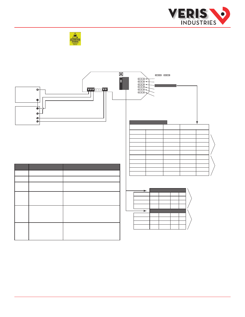
1. Find a suitable mounting position near the location to be measured. Mount the PW housing using the self-tapping screws
provided.
2. Remove the lid from the housing to reveal the board. Wire the PW terminals to the power source and to the digital control
system as shown. Configure the jumpers for desired operating parameters. Replace the cover.
JP8
JP7
JP6
JP3
JP2
JP1
ZERO
Analog Reverse/Normal
Port Swap/Normal
Bidirectional/Normal
Fast/Slow Surge Damping
5V/10V Output
mA/Volts Output
POWER
REMOTE ZERO
(Dry Contact)
DIGITAL CONTROL
Analog Input
0-5V/0-10V
or 4-20mA
Optional
Digital Output
POWER SOURCE
12 to 30 VDC/24 VAC
SIGNAL
COM
PW SERIES
/
Range
A
B
C
D
HI PORT
100 psi
100 psi
50 psi
50 psi
0 psi
LO PORT
0 psi
50 psi
50 psi
100 psi
100 psi
4-20mA
0-10V
+100 psi
+50 psi
0 psi
-50 psi
-100 psi
Bidirectional Operation
Input Conditions
Result
Outputs Read
DP
20mA
16mA
12mA
8mA
4mA
10V
7.5V
5V
2.5V
0V
17.0 bar
17.0 bar
8.5 bar
8.5 bar
0 bar
0 bar
8.5 bar
8.5 bar
17.0 bar
17.0 bar
+17.0 bar
+8.5 bar
0 bar
-8.5 bar
-17.0 bar
20mA
16mA
12mA
8mA
4mA
10V
7.5V
5V
2.5V
0V
Output is either
mA or V
e.g. PW-04
e.g. PW-08
Range (psi)
Model
PW-03
PW-04
PW-05
A
50
100
250
B
25
50
125
C
10
20
50
D
5
10
25
Range (bar)
A
3.5
7.0
17.0
B
1.75
3.5
8.5
C
0.7
1.4
3.4
D
0.35
0.7
1.7
e.g. PW-04
e.g. PW-08
Use the Range switch to
select F.S. differeintial
pressure.
Model
PW-06
PW-07
PW-08
Jumper
Options
Notes
JP1
Voltage (V) or Current (mA)
JP2
0-10V or 0-5V output span
Use only if JP1 is set to V mode.
JP3
Slow or Fast
Slow mode provides 5 second averaging for
surge damping.
JP6
Normal or Bidirectional
Normal: 0 to F.S. pressure
Bidirectional: -F.S. pressure to +F.S. pressure;
output reads 1/2 when pressure is zero.
JP7
Normal or Port Swap
Reverses polarity of the pressure ports (i.e.
makes the LO port operate as the HI port and
vice versa); used when the sensor is incorrectly
plumbed.
JP8
Normal or Analog Reverse
Normal: output increases as pressure increases;
Reverse: output is maximum when pressure
differential is zero and decreases as pressure
increases.