Installation guide, Operation, Installation – Veris Industries PXR SERIES Install User Manual
Page 2: Disconnect power to the panel, Wire, 4-20 ma, Static pressure (low port), Differ- ential pressure (high and low ports)
Z206317-0B
PAGE 2
©2012 Veris Industries USA 800.354.8556 or +1.503.598.4564 / [email protected]
09123
Alta Labs, Enercept, Enspector, Hawkeye, Trustat, Veris, and the Veris ‘V’ logo are trademarks or registered trademarks of Veris Industries, L.L.C. in the USA and/or other countries.
TM
PXR
INSTALLATION GUIDE
OPERATION
PX Series devices employ ceramic capacitive sensors and sophisticated temperature
compensation circuitry to achieve accurate pressure readings in dry media
applications. For best results, allow an initial warm-up period to ensure accuracy at
the lowest pressure ranges.
The PXR has a ZERO pushbutton to reset the output and display to zero pressure.
Press and hold the ZERO pushbutton for 2 seconds or provide contact closure on the
“AUX ZERO” terminal. To protect the unit from accidental zero, this feature is enabled
only when the detected pressure is within about 0.1 in. W.C. (25 Pa) of the factory
calibration. The optional LCD displays the current reading and the selected units.
“SET” appears each time a selection is made. “OVER” appears when the measured
pressure is over the device’s range.
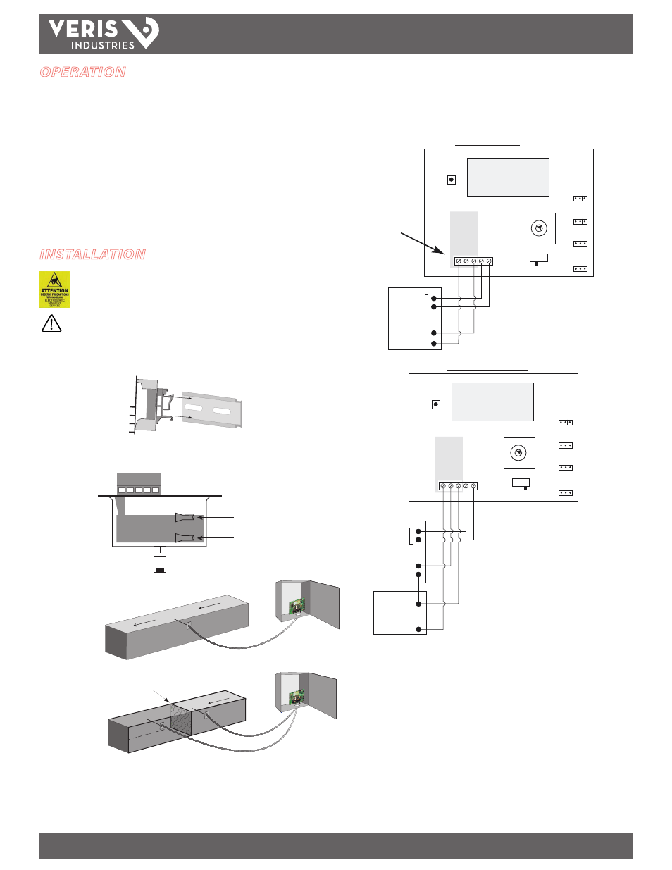
INSTALLATION
Observe precautions for handling static sensitive
devices to avoid damage to the circuitry that
is not covered under the factory warranty.
Disconnect power to the panel.
1. Select a location in the panel, near the area to be monitored. Mount the PXR onto
DIN Rail.
2. Determine the length of tubing needed for differential or static pressure. Configure
as shown:
High Port
Low Port
3.
Static
Pressure
(low port)
AIR FL
OW
Differ-
ential
Pressure
(high and
low ports)
FILTER
LOW
HIGH
AIR FLOW
Wire the PXR: connect the transmitter to the control system and the power supply
as indicated below. Optional: Connect the ZERO terminals to the digital output
(contact closure) of the control system.
2-wire, 4-20 mA
PO
WER (4-20mA
)
OUT (0-10v)
CO
M
ZERO
Volt
VOLT
OUTPUT
mA
5V/10V
JP4
MODE
BI/UNI
JP5
ZERO
DIGITAL CONTROL
Digital
Output
Return
V+
1.000
WARNING:
Do not
apply power
to output terminal!
Permanent damage
will result.
RESPONSE
FAST/STD
UNITS
IN W.C./PA
JP7
JP8
0 1
2
3 4
5
6
7
3-wire, 0-5 V/0-10 V
PO
WER (4-20mA
)
OUT (0-10v)
COM ZERO
Volt
OUTPUT
mA
ZERO
DIGITAL CONTROL
Digital
Output
V IN
-
POWER SOURCE
24VAC/DC
-
+
1.000
VOLT
5V/10V
JP4
MODE
BI/UNI
JP5
RESPONSE
FAST/STD
UNITS
IN W.C./PA
JP7
JP8
0 1
2
3 4
5
6
7