Installation, Installation guide current monitoring h931, Caution – Veris Industries H931 Install User Manual
Page 2
Z201168-0E
Page 2 of 4
©2013 Veris Industries USA 800.354.8556 or +1.503.598.4564 / [email protected] 08131
Alta Labs, Enercept, Enspector, Hawkeye, Trustat, Aerospond, Veris, and the Veris ‘V’ logo are trademarks or registered trademarks of Veris Industries, L.L.C. in the USA and/or other countries.
Other companies’ trademarks are hereby acknowledged to belong to their respective owners.
Installation Guide
Current Monitoring
H931
TM
Disconnect and lock out power to the enclosure containing the conductor to be
monitored.
1. Locate a mounting surface for the removable mounting bracket
that will allow the monitored conductor to pass through the center
window when it is installed and that will keep the product at least
½” (13 mm) from any uninsulated conductors. Determine cable
routing for the controller connection, allowing wiring to reach the
mounting location. If using with a variable frequency drive, then
mount the sensor on the line side.
2. Drill holes to mount the bracket to the chosen surface using the
included screws.
3. Set the desired amperage range (30, 60, or 120 Amps).
4. Wire the output connections between the sensor and the controller
(4-20mA).
5. Snap the sensor over the wire to be monitored and clip the assembly
to the mounting bracket.
6. Scale the controller software to match the sensor’s output.
7. Secure the enclosure and reconnect power.
Installation
Fan or Pump
CONTROLLER
Motor
CONTACTOR
AI
(4-20mA)
DO
(Relay Coil)
CONTROL POWER
12-30 VDC
Power Source
Notes
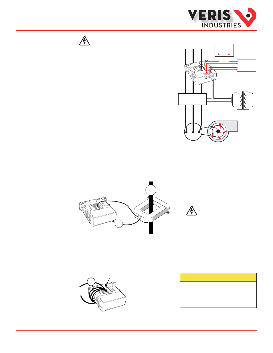
For load currents greater than sensor maximum rating:
Use a 5 Amp (H68xx series) current transformer (CT) as shown. This technique can be combined with wrapping (see below) to add
range for a low current load on a high current source.
DANGER: 5A CTs can present
hazardous voltages. Install
CTs in accordance with
manufacturer's instructions.
Terminate the CT secondary
before applying current.
CAUTION
RISK OF EQUIPMENT DAMAGE
• Derate the product’s maximum current for the number of turns
through the sensing window using the following formula.
Rated Max. Amps ÷ Number of Turns = Max. monitored Amps
e.g. : 100A ÷ 4 Turns = 25 Amps max. in monitored conductor
• Failure to follow these instructions can result in overheating
and permanent equipment damage.
4x
1A
H68xx-5A CT
240A
300A:
5A
4A
>120 A (sensor max.)
< 1.5 A (Sensor Min.)
For load currents less than sensor minimum rating:
Wrap the monitored conductor through the center window and around the sensor body to produce multiple turns. This increases
the current measured by the transducer. Program the controller to account for the extra turns (e.g., if four turns pass through the
sensor (as shown), divide the normal reading by 4).