Spicer Single Speed Axle - Service Manual User Manual
Page 23
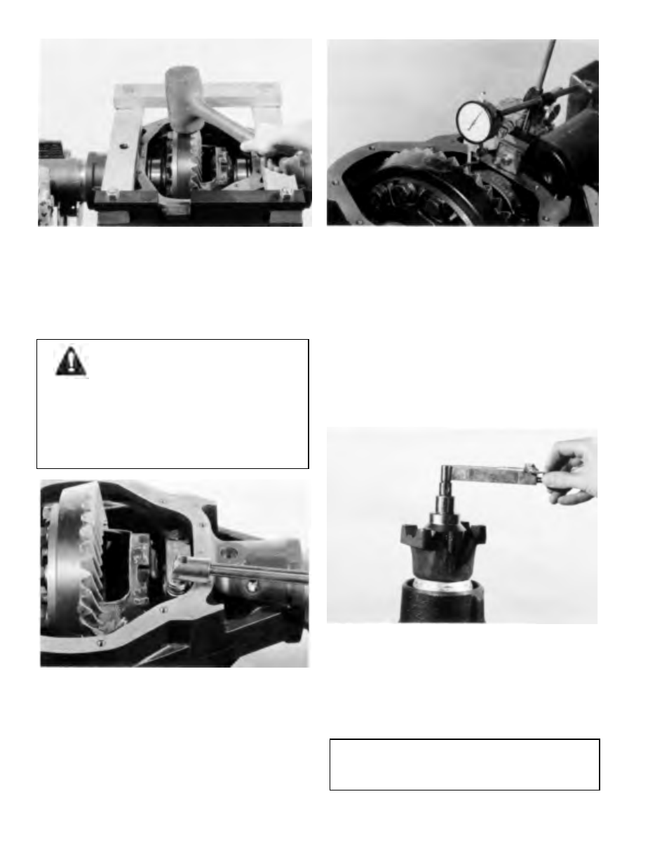
Figure 3-46
Step (47) Assemble differential bearing cups to differential
bearing cones. Install differential assembly into carrier. Use
a rawhide or plastic hammer to seat differential assembly
into cross bores of carrier. Care should be taken to avoid
nicking the teeth of the ring gear and pinion during
assembly. Remove spreader.
WARNING: When differential assembly is
installed into carrier, use care to avoid
pinching hand or fingers between
differential bearing cup and carrier
housing.
Gear teeth may have sharp edges. When
handling gear, use care to avoid cutting
hands.
Figure 3-47
Step (48) Install bearing caps. Make sure the letters
stamped on the caps correspond with those on the carrier.
Torque bearing cap screws to specification.
TOOL: Torque Wrench
3-14
Figure 3-48
Step (49) Check ring gear and pinion backlash in three
equally spaced points with dial indicator as shown.
Backlash should be within specification and cannot vary
more than .002 (-05 mm) between points checked.
TOOL: C-3339 Dial Indicator Set
High backlash is corrected by moving the ring
gear closer to the pinion.
Low backlash is corrected by moving the ring gear
away from the pinion.
These corrections are made by switching shims
from one side of the differential case to the other.
Figure 3-49
Step (50) Using an in. lb. torque e wrench as shown, rotate
pinion and differential assembly, Torque reading should
be within specifi ication. If preload is to high, remove an
equal amount of shims from both sides of the differential
case hubs. If preload is to low, add an equal amount of
shims to both sides of differential case hubs.
NOTE
If shims are added to one side only, it will affect
backlash reading.