Spicer Single Speed Axle - Service Manual User Manual
Page 19
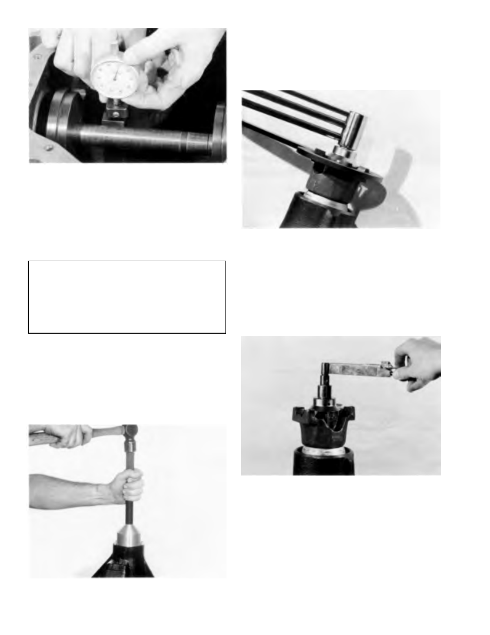
Figure 3-34
Step (36) Place arbor and discs (large diameter end) into
cross bore of carrier. Place pinion height block on button
end of pinion. Set dial indicator on height block (high step
of block). Set dial indicator at zero (0). Slide scooter gage
across or over arbor.
Indicator will read a plus (+) or minus (-) at its highest
point, depending on the etching of the pinion.
NOTE
Indicator reading within .002 (.05 mm) of etching is
considered acceptable. If pinion position is found to
be within specification, continue with build-up. If pinion
position is not within specification, change shim pack
thickness under inner bearing cup.
Remove pinion nut, washer, end yoke, and pinion.
Assemble preload shims onto pinion.
NOTE: If old shims are available, measure shim pack and
build up new shim pack using new shims of the same
thickness. If old shim pack is not available for reference,
build shim pack up to .060 (1.52 mm) thick. This will
provide a starting point and may require adjustment.
Figure 3-35
Step (37) Apply a light coat of hypoid lubricant on the lip
of pinion seal and assemble into carrier.
TOOL: 8152 Seal Installer
C-4171 Handle
Figure 3-36
Step (38) Assemble pinion, end yoke, washer, and new
pinion nut. Torque nut to specification.
TOOL: 6719 Yoke Holder
Torque Wrench
NOTE: Torque wrench must be capable of 500 lbs. ft. (677.9
N•m) torque.
Figure 3-37
Step (39) Using an in. Lbs. torque wrench as shown, rotate
pinion. Torque to rotate pinion should be within
specification. To increase preload, remove shims, to
decrease preload add shims.
3-10