Spicer Single Speed Axle - Service Manual User Manual
Page 10
SECTION 3
CARRIER SECTION
DISASSEMBLY
NOTE
The photos or pictures contained herein are
for illustrative and instructional purposes only. The
appearance of your axle assembly and/or
components may vary from that shown. However,
the service procedures described will apply.
If it becomes necessary to disassemble any
parts inside the carrier, it is suggested that the entire
axle be removed from the vehicle and held tight in
a stand or rack.
All dimensions are in inches unless otherwise
stated. Dimensions in parentheses followed by mm
are in millimeters.
WARNING: When removing axle assembly,
make sure vehicle is properly supported.
Improperly supported vehicle can cause
serious injury or death. Follow vehicle
manufacturers recommendations for
proper axle assembly removal
procedures.
Step (1) Remove cover plate from housing and drain
lubricant.
NOTE
Before removing differential case assembly, make
sure the axle shafts are pulled out far enough for
clearance to allow removal.
Figure 3-1
Step (2) Remove bearing caps. Note mating letters stamped
on caps and carrier. This is important at time of assembly
as they are to be assembled exactly as removed. Letters or
numbers are in vertical and horizontal position.
Figure 3-2
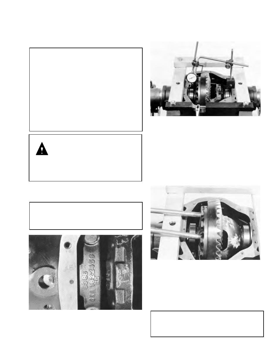
Step (3) Mount spreader to housing. DO NOT SPREAD
CARRIER OVER ,015 (.38 mm). Use dial indicator as
shown.
TOOL: W- 129-B Differential Spreader
C-3339 Dial Indicator Set
Figure 3-3
Step (4) Pry differential case from carrier with two pry
bars. After differential case has been removed, remove
spreader. Use caution to avoid damage to components.
Tag bearing cups indicating from which side they were
removed from. See note below regarding the use of
bearings.
NOTE
It is recommended that whenever bearings are
removed, they are to be replaced with new ones,
regardless of mileage.
3-1