Ring gear removal, Servicing standard differential case assembly, Case disassembly – Spicer Single Speed Axle - Service Manual User Manual
Page 11
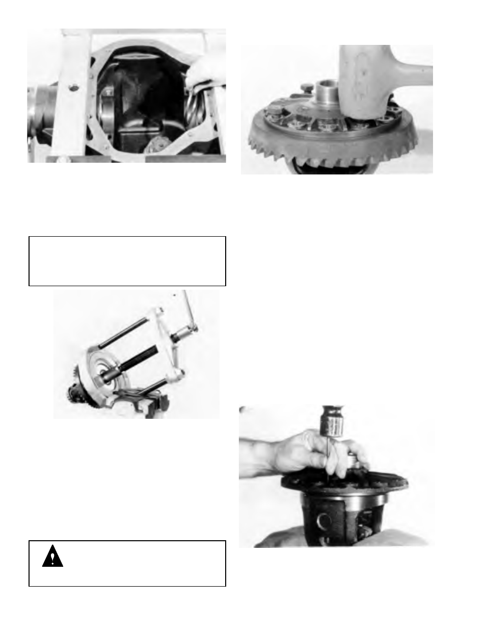
Figure 3-4
Step (5) Note the differential bearing outboard spacers
located on each side of the differential bearing bore.
Remove and tag which side they were removed from. Ring
gear side or opposite side. They will be reused during
assembly, unless damaged or worn.
NOTE
Check outboard spacers for damage. (e.g. caused
by worn bearings). If damaged, they should be
replaced with new ones at time of reassembly.
Figure 3-5
Step (6) Remove differential bearing cones with a puller
as shown. Tag cones indicating from which side they were
removed from.
TOOL:
DD-914 Press
DD-914-99 Adapters
DD-914-8 Adapter Ring
DD-914-7 Extension
DD-914-42 Button
WARNING: When pulling bearings, do
not allow differential assembly to fall. It
can strike legs or feet and may cause
serious injury.
RING GEAR REMOVAL
Figure 3-6
Step (7) Place differential case in vise or suitable holding
fixture. Remove ring gear screws. Leave 4 screws loosely
assembled 90 degrees apart. Place assembly on a solid
bench. Tap screws alternately and evenly to free ring gear
from differential case. Remove screws and ring gear.
Discard ring gear screws. Ring gear screws are to be
replaced with new ones at time of reassembly.
SERVICING STANDARD
DIFFERENTIAL CASE ASSEMBLY
The differential assembly may be serviced at this time, if
required. If differential case, side gears and pinion mate
gears are useable and do not require servicing, proceed to
DRIVE PINION REMOVAL.
CASE DISASSEMBLY
Figure 3-7
Step (8) Remove roll pin with a small drift.
3-2