Spicer Single Speed Axle - Service Manual User Manual
Page 21
3-12
face of the case is free of nicks or burrs. Assemble ring
gear to case. Line up holes of the ring gear with those of
the case. Use new ring gear screws. Draw up screws
alternately and evenly. Torque ring gear screws to
specification.
TOOL: Torque Wrench
Figure 3-42
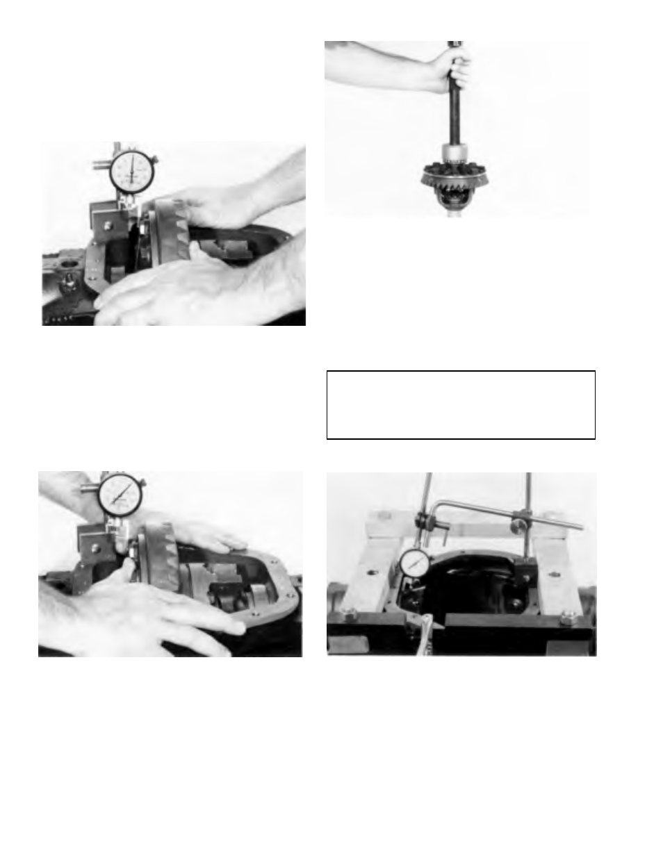
Step (43) Assemble master differential bearings onto case
hubs. Place differential assembly into housing. Set up dial
indicator as shown. Locate tip of indicator on flat surface
of one of the ring gear screws. Force the differential case
assembly (ring gear) away from the pinion gear. With force
still applied to the differential case, set indicator at zero
“0”.
TOOL: C-3339 Dial Indicator Set
Figure 3-43
Step (44) Force the differential case assembly and ring
gear into mesh with the pinion gear. Rock ring gear to allow
the teeth of the gear to mesh. Repeat until the same reading
is obtained each time. Record this reading on the
worksheet, page 313. This reading will be measurement
“B”. Remove indicator and differential case assembly from
the carrier. Remove master differential bearings from the
differential case. Refer to the worksheet for calculating
ring gear backlash and differential bearing preload shims,
page 3-13.
Figure 3-44
Step (45) Assemble the required amount of shims onto
hub (ring gear side) and opposite side as determined using
the worksheet. Place bearing cone on hub of case. Use
bearing installer to seat bearing cone as shown.
TOOL:
C- 1490 Installer
C-4171 Handle
DD-914-42 Button
NOTE
Button is used to raise case from bench to protect
bearing cone cage from being damaged when
installing opposite bearing cone.
Figure 3-45
Step (46) Install spreader and indicator as shown. DO NOT
SPREAD CARRIER OVER .015 (.38 mm). Remove indicator.
TOOL: W- 129 B Differential Spreader
C-3339 Dial Indicator Set