Spicer Single Speed Axle - Service Manual User Manual
Page 15
On the button end of each pinion, there is etched
a plus (+) number, a minus (-) number, or a zero (0)
which indicates the best running position for each par-
ticular gear set. This dimension is controlled by the
shimming behind the inner pinion bearing cup.
For example: If a pinion is etched a plus +3 (m+8),
this pinion would require .003 (.08 mm) less shims
than a pinion etched “0”. This means by removing
shims, the mounting distance of the pinion is in-
creased to 3.503 (88.98 mm), which is just what a +3
(m+8) indicates. Or if a pinion is etched -3 (m-8), we
would want to add .003" (.08 mm) more shims than
would be required if the pinion were etched “0”. By
adding .003 (08 mm) shims, the mounting distance
of the pinion was decreased to 3.497 inches (88.82
mm) which is just what a -3 (m-8) indicates.
If the old ring and pinion set is to be reused, mea-
sure the old shim pack and build a new shim pack to
this same dimension. If a baffle is used in the axle
assembly, it is considered as part of the shim pack.
To change the pinion adjustments, use different
combination of the pinion shims which come in
different thicknesses.
NOTE
If baffle or slinger is bent or mutilated, it should be
replaced.
Measure each shim separately with a microme-
ter and add together to get total shim pack thickness
from the original build-up.
If a new gear set is being used, notice the (+) or
(-) etching on both the old and new pinion and adjust
the thickness of the new shim pack to compensate
for the differences of these two figures.
For example: If the old pinion reads +2 (m+5) and
the new pinion is -2 (m-5), add .004" (. 10 mm) shims
to the original shim pack.
Figure 3-19 (Pinion Setting Chart - English U.S.
Standard)
Figure 3-20 (Pinion Setting Chart - Metric)
If metric, pinion will be etched (m+ some num-
ber). Example (m+5). Use these charts as a guideline
to set pinion.
ESTABLISHING PINION GEAR
DEPTH USING SERVICE TOOL
GAGES.
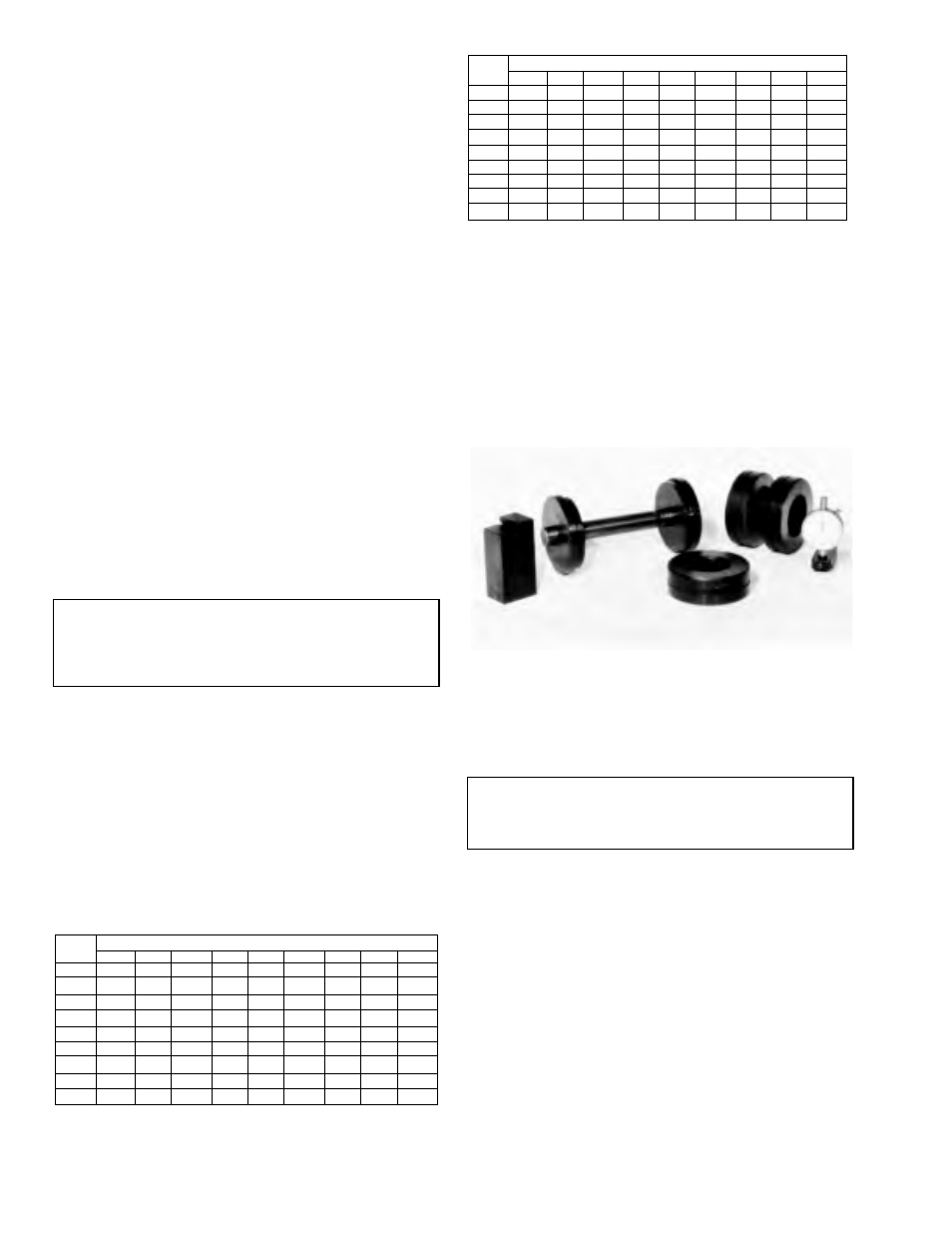
Figure 3-21
View of master pinion bearing, pinion height
block, scooter gage, cross arbor, arbor discs and
master differential bearings.
NOTE
Make sure that all carrier bores are free from all
nicks, dirt or any other contamination.
3-6
-10
-8
-5
-3
0
+3
+5
+8
+10
+10
+.20
+.18
+.15
+.13
+.10
+.08
+.05
+.03
0
+8
+.18
+.15
+.13
+.10
+.08
+.05
+.03
0
-.03
+5
+.15
+.13
+.10
+.08
+.05
+.03
0
-.03
-.05
+3
+.13
+.10
+.08
+.05
+.03
0
-.03
-.05
-.08
0
+.10
+.08
+.05
+.03
0
-.03
-.05
-.08
-.10
-3
+.08
+.05
+.03
0
-.03
-.05
-.08
-.10
-.13
-5
+.05
+.03
0
-.03
-.05
-.08
-.10
-.13
-.15
-5
+.03
0
-.03
-.05
-.08
-.10
-.13
-.15
-.18
-10
0
-.03
-.05
-.08
-.10
-.13
-.15
-.18
-.20
New Pinion Marking
Old Pinion
Marking
-4
-3
-2
-1
0
+1
+2
+3
+4
+4
+0.008
+0.007
+0.006
+0.005
+0.004
+0.003
+0.002
+0.001
0
+3
+0.007
+0.006
+0.005
+0.004
+0.003
+0.002
+0.001
0
-.0.001
+2
+0.006
+0.005
+0.004
+0.003
+0.002
+0.001
0
-.0.001
-0.002
+1
+0.005
+0.004
+0.003
+0.002
+0.001
0
-.0.001
-0.002
-0.003
0
+0.004
+0.003
+0.002
+0.001
0
-.0.001
-0.002
-0.003
-0.004
-1
+0.003
+0.002
+0.001
0
-.0.001
-0.002
-0.003
-0.004
-0.005
-2
+0.002
+0.001
0
-.0.001
-0.002
-0.003
-0.004
-0.005
-0.006
-3
+0.001
0
-.0.001
-0.002
-0.003
-0.004
-0.005
-0.006
-0.007
-4
0
-.0.001
-0.002
-0.003
-0.004
-0.005
-0.006
-0.007
-0.008
New Pinion Marking
Old Pinion
Marking