Ring & pinion gear assembly theory – Spicer Single Speed Axle - Service Manual User Manual
Page 14
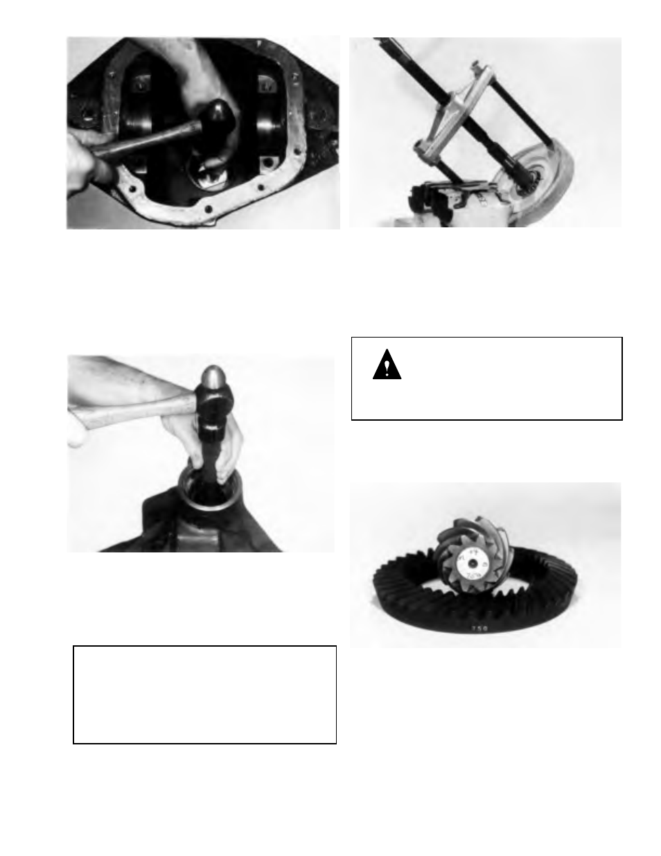
Figure 3-15
Step (20) Turn nose of carrier down. Remove outer pinion
bearing cup. Locate driver on back edge of cup; drive cup
out of carrier. CAUTION: DO NOT NICK CARRIER BORE.
TOOL:
D-159 Pinion Bearing Cup Remover
C-4171 Handle
Figure 3-16
Step (21) Remove the inner bearing cup with tools as shown.
TOOL:
C-4307 Bearing Cup Remover
C-4171 Handle
NOTE:
Shims are located between the bearing cup and
carrier bore and may also include an oil baffle,
depending upon the application. If shims and baffle
are bent or nicked, they should be replaced at time
of assembly.
Figure 3-1 7
Step (22) Remove pinion bearing with tools as shown.
TOOL:
DD-914-P Press
DD-914-8 Adapter Ring
DD-914-95 Adapters
WARNING: Do not allow gear to fall. It can
strike legs or feet and may cause serious
injury. Gear teeth may have sharp edges.
When handling, use care to avoid cutting
hands.
RING & PINION GEAR
ASSEMBLY THEORY
Figure 3-18 (View of ring 81 pinion set)
Step (23) Ring gears and pinions are supplied in matched
sets only. Matching numbers on both the pinion and ring
gear are etched for verification. If a new gear set is being
used, verify the numbers of each pinion and ring gear before
proceeding with assembly.
The nominal distance from the centerline of the ring
gear to the button end of the pinion for the Model 80 axle
is 3.500 (88.9 mm).
3-5