Assembly of differential – Spicer Single Speed Axle - Service Manual User Manual
Page 20
3-11
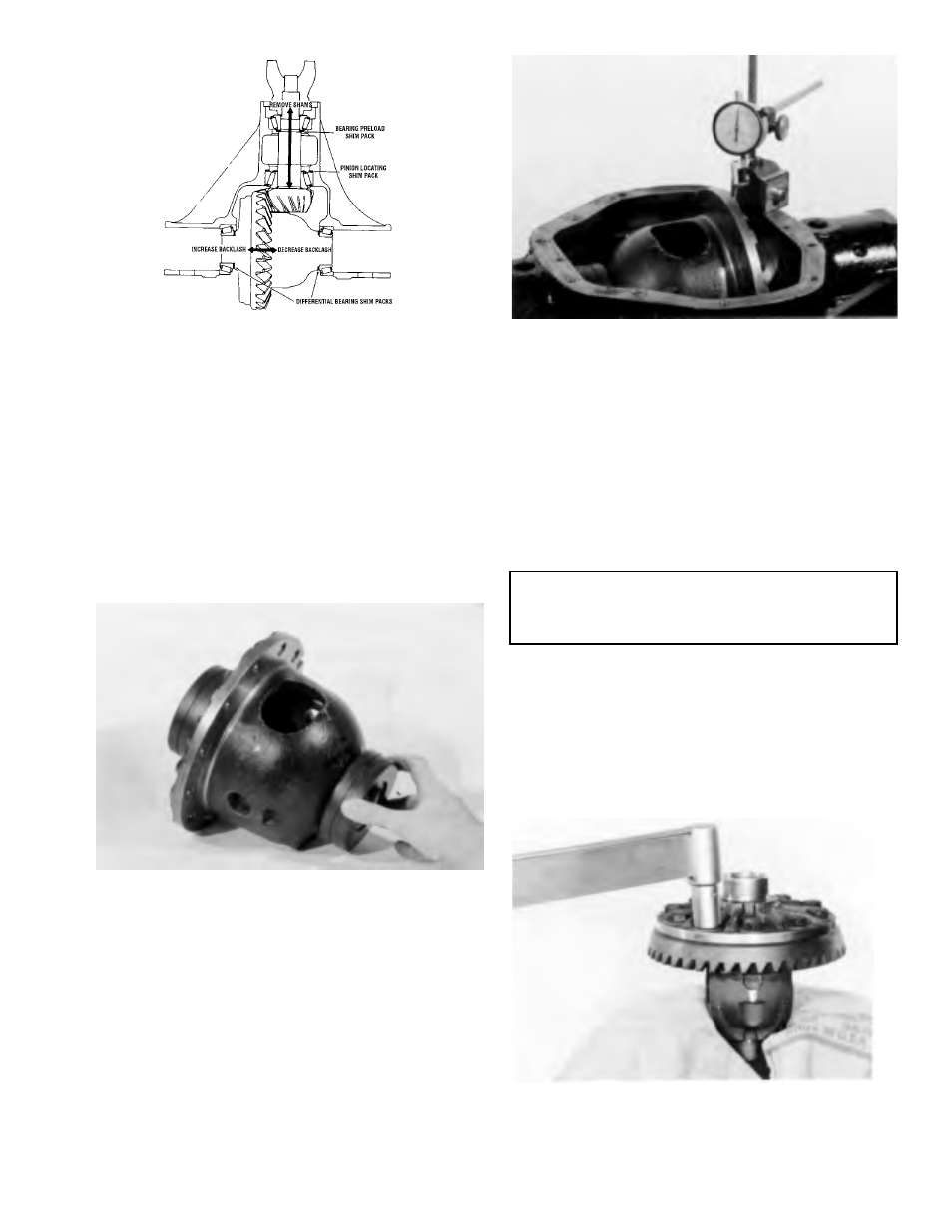
Figure 3-38
The illustration in figure 338 shows the arrow in the pinion
pointing in two directions. The direction pointing towards
the end yoke indicates that by removing pinion position
shims, the distance from the centerline of the axle to the
pinion button is increased giving a plus reading. The preload
shim pack does not effect the pinion depth setting. Arrows
on the ring gear illustrate the method to increase or
decrease backlash and differential bearing preload.
ASSEMBLY OF DIFFERENTIAL
Figure 3-39
Step (40) Assemble master differential bearings onto case.
Remove all nicks, burrs, dirt etc., from hubs to allow master
bearings to rotate freely.
TOOL: 6776 Dummy Differential Bearing Set
Figure 3-40
Step (41) Assemble the differential bearing outboard
spacers into the carrier housing, as removed in step 5,
figure 34.
Assemble differential case into carrier (less ring gear).
Mount dial indicator with a magnetic base as shown. Locate
tip of indicator on flat surface of case. Force differential
assembly as far as possible in the direction towards the
indicator. With force still applied, set indicator at zero (0).
TOOL: C-3339 Dial Indicator Set
NOTE
Dial indicator should have a minimum travel capability
of .200 (5.08 mm).
Force the differential assembly as far as it will go in
the opposite direction. Repeat these steps until you have
obtained the same reading. Record the reading of the
indicator on the worksheet, page 313. This reading will be
measurement “A”. After making sure the readings are
correct, remove indicator and differential assembly from
housing. Remove master bearings from hubs and set aside.
Figure 3-41
Step (42) Place case assembly in a vise. Be sure flange