Ring gear and pinion tooth pattern, Correct gear patterns for orlikon cut gears – Spicer Tandem Drive Axles Service Manual S400 User Manual
Page 26
24
RING GEAR AND PINION
TOOTH CONTACT PATTERN
CORRECT GEAR PATTERNS FOR GLEASON CUT GEARS
HEAVILY LOADED
LIGHTLY LOADED
The procedures to the right are to be used to establish
proper gear tooth pattern after assembly of the carrier is
complete.
NOTE: If matched sets are being reused, measure and
record backlash before disassembly, and reas-
semble to the same backlash. This will match ring
and pinion gears to the established wear patterns.
Hand rolled patterns will cover less area than the
gear pattern established by previous service.
The GLEASON gear set is identified by a 390GA
100
series part number. The ORLIKON is identified by a
390GA
200 series part number. (See Gear Set Identifi-
cation section.)
NOTE: Tooth contact pattern, on this axle model, can be moved only by adjusting backlash. The contact
pattern can be moved in the direction of heel-to-toe, and toe-to-heel; Depth of the pattern cannot be
adjusted. If an acceptable tooth contact pattern cannot be established within limits of backlash, contact
Spicer Service at 1-800-666-8688.
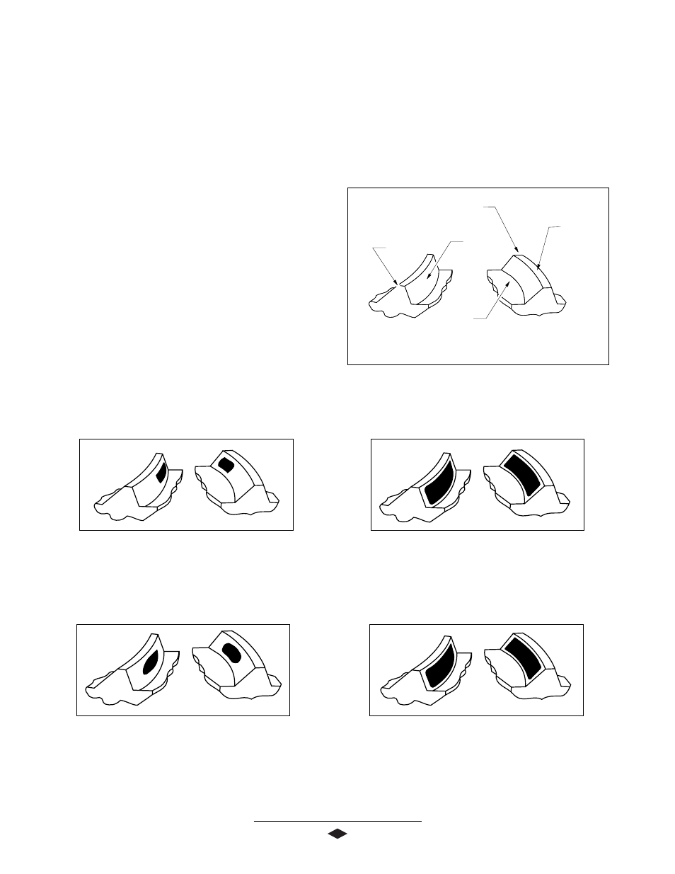
CORRECT GEAR PATTERNS FOR ORLIKON CUT GEARS
HEAVILY LOADED
LIGHTLY LOADED
TOE
HEEL
ROOT
DRIVE SIDE
(CONVEX)
COAST SIDE
(CONCAVE)
PROFILE
TOP LAND
STEP 1. Paint 1/4 ring gear with marking compound on
both the drive and coast side.
STEP 2. Rotate ring gear at least one complete
revolution in both directions while load is
being applied.