Ogramming input – American Magnetics 12200PS DC Power Supply (CE-Marked) User Manual
Page 48
OPERATING MANUAL
REMOTE OPERATION
Release 1.0 (98/07)
4-3
4.2.3
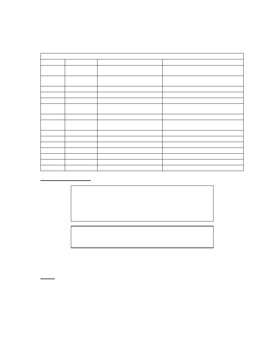
Rear Panel J2 Connector (continued)
See Table 4.2-2 for the
list of the J2 connector terminal numbers, their labels, and corresponding functions.
Table 4.2-2 Rear Panel J2 Connector Terminals and Functions
Connector
Label
Name
Function
J2-1
VRMT
Remote Output Voltage
Programming Select
Selects remote output voltage
programming when jumpered to pin 3.
J2-2
IRMT
Remote Output Current Limit
Programming Select
Selects remote output current limit
programming when jumpered to pin 3.
J2-3
CNTL GND
Control Ground
Control ground.
J2-4
N/C
No connection
None.
J2-5
VPGM –
Voltage Program Signal Return
Return for voltage program signal.
J2-6
VPGM
Output Voltage Programming
Input
Input for voltage programming signals from
an analog device.
J2-7
IPGM –
Current Program Signal Return
Return for current program signal.
J2-8
IPGM
Output Current Limit
Programming Input
Input for current limit programming signals
from an analog device.
J2-9
VMON –
Voltage Monitor Signal Return
Return for voltage monitor signal.
J2-10
VMON
Output Voltage Monitor
Output for output voltage monitor signal.
J2-11
IMON –
Current Monitor Signal Return
Return for current monitor signal.
J2-12
IMON
Output Current Monitor
Output for output current monitor signal.
J2-13
N/C
No connection
None.
J2-14
S/D –
Shutdown Signal Return (-)
Return for shutdown signal.
J2-15
S/D
S/D Input (+)
Input for shutdown signal.
Making J2 Connections
CAUTION
Do not attempt to bias program/monitor signal return (J2 terminals 5, 7, 9,
and 11) relative to the supply output because control ground (J2-3) and the
program/monitor signal returns are at the same potential as the power
supply return in a standard unit. Use the Isolated Programming (ISOL)
Interface option to allow control from a programming source at a different
potential relative to the supply’s output.
CAUTION
To maintain the isolation of the power supply output and prevent ground
loops, use an isolated (ungrounded) programming source when operating
the power supply via remote analog control at the J2 connector.
Make connections to the J2 connector using its screw-type wire clamps. Before making any connections, turn the
power supply OFF and wait until the front panel displays have gone out. You can unplug the connector from the
back of the unit in order to make it easier to install the required wiring.
Wiring
Use any suitable wire such as 16 to 24 AWG stranded wire for most connections, but we recommend that you
use shielded twisted pair wiring for applications which require low noise performance. Strip wires 0.26"
(6.5 mm) and insert securely, as with any wire clamp connector.