Local and remote sensing, 8 local and remote sensing -17, 1 sense wiring -17 2.8.2 local sensing -17 – American Magnetics 12200PS DC Power Supply (CE-Marked) User Manual
Page 32: Figure 2.8-1 j10 sense connector -17, Ection 2.8 local and r, 8 local and remote sensing
OPERATING MANUAL
INSTALLATION
Release 1.0 (98/07)
2-17
2.8 Local and Remote Sensing
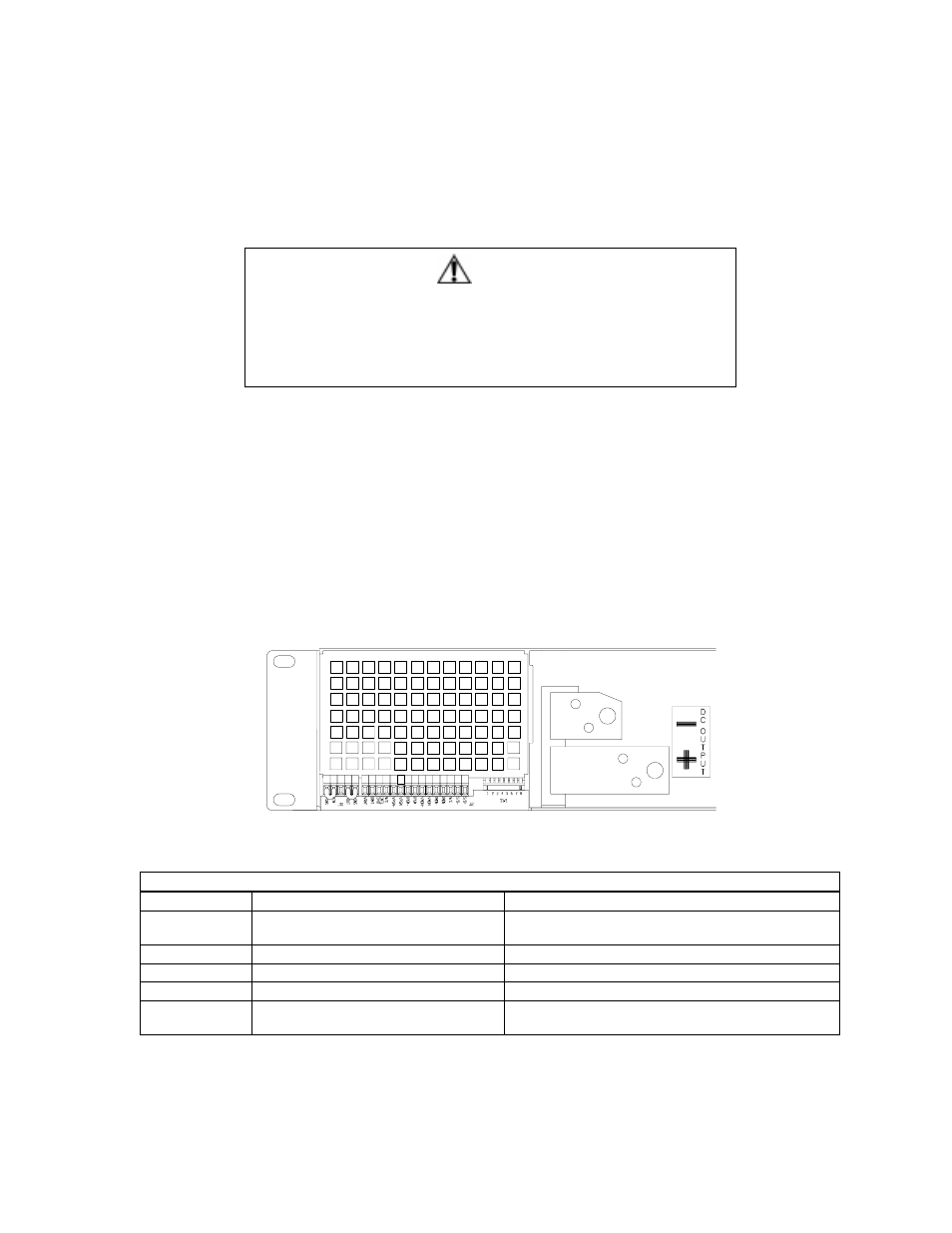
Use connections at the rear panel J10 sense connector to configure the
power supply for local or remote sensing
of output voltage. See Figure 2.8-1 for a drawing of the sense connector.
2.8.1 Sense
Wiring
WARNING
There is a potential shock hazard at the sense connector when using a
power supply with a rated output greater than 40V. Select wiring with a
minimum insulation rating equivalent to the maximum output voltage of the
power supply for use as local sense jumpers or for remote sense wires. For
example, select TEW-105, 105°C, 600V wiring for use with a model 600-4
power supply.
For lowest noise performance, use shielded-twisted pair wiring of 16 to 24 AWG for remote sense lines. Strip
wires 0.26" (6.5 mm) and insert securely as with any wire clamp connector.
2.8.2
Local Sensing
We ship the
power supply with the rear panel J10 sense connector jumpered for local sensing of the output
voltage. See Table 2.8-1 for the list of connector functions and a description of local sense connections. With
local sensing, the output voltage is regulated at the output terminals (or bus bars). This method does not
compensate for voltage losses in the load lines, so it is recommended only for low current applications or
applications for which load regulation is not essential.
Note:
When using local sense connections, use the largest practical load wire size to minimize the effects of
line impedance on the regulation of the supply.
Figure 2.8-1 J10 Sense Connector
(Shown with local sense jumpers connected.)
Table 2.8-1 Rear Panel J10 Sense Connector Terminals and Functions
Terminal
Name
Function
J10-1
Return Sense (-SNS)
Remote negative sense connection. Default
connection to terminal 2.
J10-2
Negative Output ( Return or RTN)
Connected internally to negative bus bar.
J10-3
N/C
No connection.
J10-4
Positive Output (+OUT)
Connected internally to positive bus bar.
J10-5
Positive Sense (+SNS)
Remote positive sense connection. Default
connection to terminal 4.