English – ASRock Fatal1ty P67 Professional User Manual
Page 33
33
Fatal1ty P67 Professional Series Motherboard
English
SA
TA2_3 SA
TA2_5
SA
TA2_2 SA
TA2_4
Serial ATA (SATA)
Either end of the SATA data
Data Cable
cable can be connected to the
(Optional)
SATA / SATAII / SATA3 hard
disk or the SATAII / SATA3
connector on this motherboard.
SA
TA3_M4 SA
TA3_M2 SA
TA3_1
SA
TA3_M3 SA
TA3_M1 SA
TA3_0
We recommend to use Intel
®
P67 SATA ports (SATA3_0, SATA3_1,
SATA2_2, SATA2_3, SATA2_4 and SATA2_5) for your bootable
devices. This will minimum your boot time and get the best
performance. But if you still want to boot from Marvell SATA3
controller, you can still enable
Marvell SATA3 Bootable
in UEFI. If
you want to install USB 3.0 device on Marvell SATA3 port, please use
SATA3_M1 and SATA3_M2 as the fi rst priority for better performance.
Serial ATAII Connectors
These four Serial ATAII (SATAII)
(SATA2_2: see p.4, No. 14)
connectors support SATA data
(SATA2_3: see p.4, No. 13)
cables for internal storage
(SATA2_4: see p.4, No. 12)
devices. The current SATAII
(SATA2_5: see p.4, No. 11)
interface allows up to 3.0 Gb/s
data transfer rate.
Serial ATA3 Connectors
These six Serial ATA3 (SATA3)
(SATA3_0: see p.4, No. 16)
connectors support SATA data
(SATA3_1: see p.4, No. 15)
cables for internal storage
(SATA3_M1: see p.4, No. 18)
devices. The current SATA3
(SATA3_M2: see p.4, No. 17)
interface allows up to 6.0 Gb/s
(SATA3_M3: see p.4, No. 20)
data transfer rate. If you install
(SATA3_M4: see p.4, No. 19)
the HDD on the eSATA port on
the rear I/O, the internal
SATA3_M4 will not function.
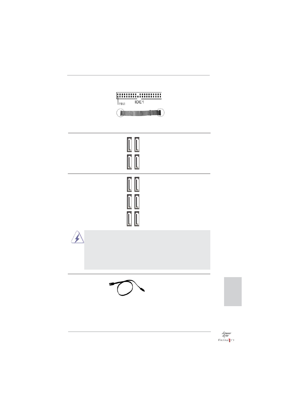
Primary IDE connector (Black)
(39-pin IDE1, see p.4 No. 9)
Note: Please refer to the instruction of your IDE device vendor for the details.
connect the black end
to the IDE devices
connect the blue end
to the motherboard
80-conductor ATA 66/100/133 cable