Figure 14. me406p elt outline and dimensions – ACR&Artex ME406 Portable ELT User Manual
Page 52
ARTEX PRODUCTS / ACR ELECTRONICS, INC
DESCRIPTION, OPERATION, INSTALLATION AND MAINTENANCE MANUAL
ME406P (453-6611)
25-62-31
Page 52 of 85
JUN 25/13
(1)
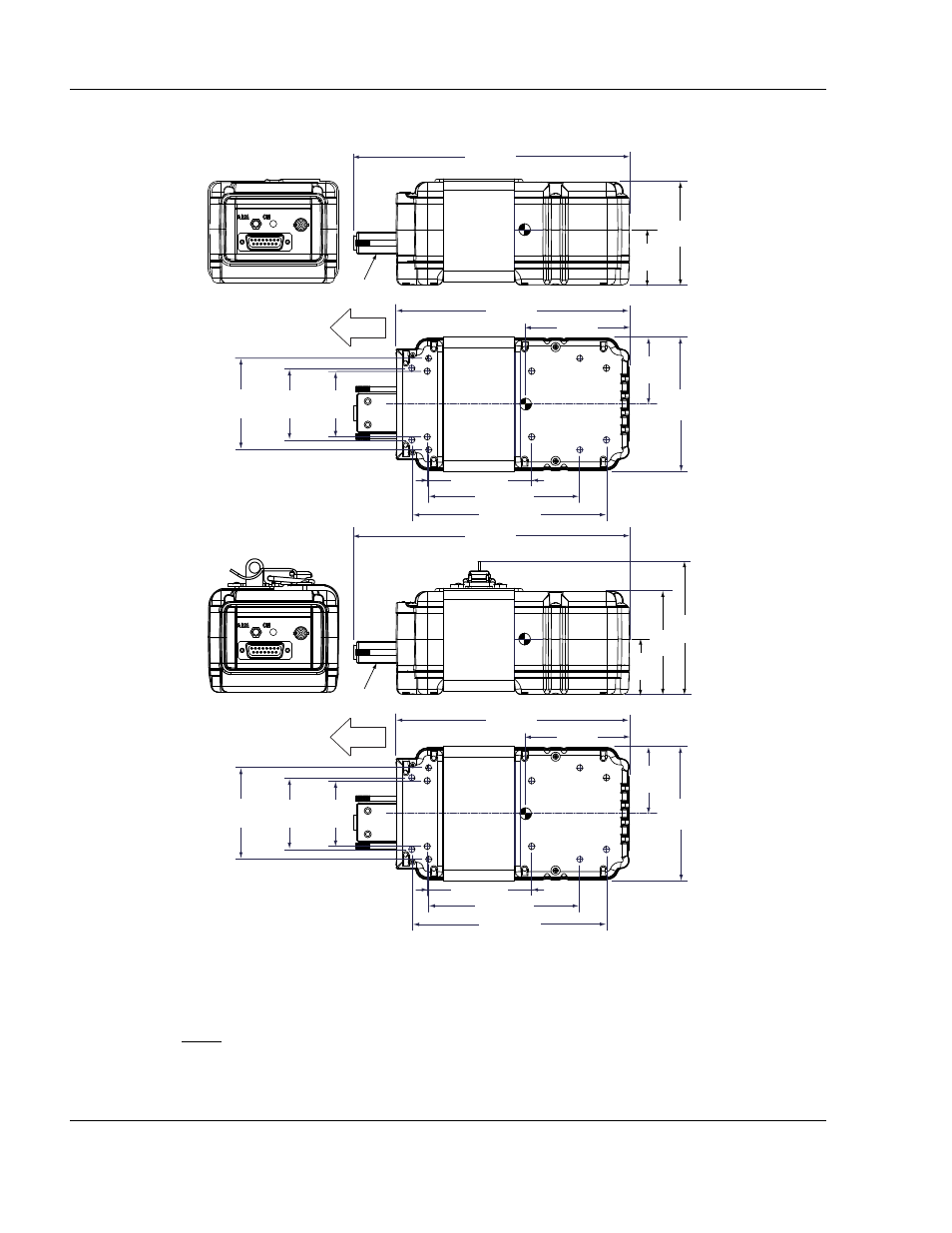
Select a suitable location for the ELT mounting tray. See Figure 14. ME406P ELT Outline and
Dimensions. Refer to these dimensions when determining mounting location.
Figure 14. ME406P ELT Outline and Dimensions
(2)
Mount the ELT as far aft as practical, but where it can be easily retrieved for maintenance.
NOTE: Statistics show that the tail section of an airplane is likely to be less damaged during
a crash; therefore, providing a good mounting environment for the ELT.
(3)
Additional installation guidance may be found in AC 43.13-2, Chapter 2, Paragraph 28, which
specifically addresses ELT installations.
3.00 (76)
6.60 (168)
[A] 5.50 (140)
[C] 4.27 (108)
[B] 2.95 (75)
1.83
(46)
[B]
2.00
(51)
[A]
2.55
(65)
[C]
1.84
(47)
3.69
(94)
7.80 (198)
1.54
(39)
2.86
(73)
MOUNTING HOLES CAPABILITY:
[A] ARTEX 110 SERIES, NARCO, & NEW
[B] ARTEX 200 SERIES
[C] POINTER MODEL 3000
Dimensions in inches (mm)
D-SUB
HOUSING
FLIGHT
3.00 (76)
6.60 (168)
[A] 5.50 (140)
[C] 4.27 (108)
[B] 2.95 (75)
1.83
(46)
[B]
2.00
(51)
[A]
2.55
(65)
[C]
1.84
(47)
3.69
(94)
7.80 (198)
1.54
(39)
2.86
(73)
3.77
(96)
MOUNTING HOLES CAPABILITY:
[A] ARTEX 110 SERIES, NARCO, & NEW
[B] ARTEX 200 SERIES
[C] POINTER MODEL 3000
Dimensions in inches (mm)
D-SUB
HOUSING
FLIGHT