Rmc 5018 – Acnodes RMC 5018 User Manual
Page 40
© Copyright 2011 Acnodes, Inc.
All rights reserved. Product description and product specifications
are subject to change without notice. For latest product information,
please visit Acnodes’ web site at www.acnodes.com.
14628 Central Blvd,
Chino, CA91710
tel:909.597.7588, fax:909.597.1939
RMC
1U Rackmount
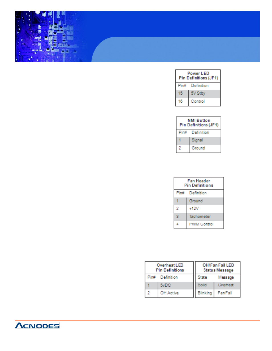
Power LED
The Power LED connector is located on pins 15
and 16 of JF1. This con- nection is used to
provide LED indica- tion of power being sup-
plied to the system. See the table on the right
for pin definitions.
NMI Button
The non-maskable interrupt button header is
located on pins 19 and 20 of JF1. Refer to the
table on the right for pin definitions.
Fan Headers
The embedded board has two fan headers.
Fan1 is the CPU fan and Fan2 is for the system
cooling fan. These fans are 4-pin fan headers.
However, Pins
1~3 of the fan headers are backward compatible
with the traditional 3-pin fans. (The speeds of 4-
pin (PWM) fans are controlled by Thermal Man-
agement via BIOS Hardware Moni- toring in
the Advanced Setting. (The default setting is
Disabled.) Note: Please use all 3-pin fans or all
4-pin fans on a motherboard. Please do not use
3-pin fans and 4-pin fans on the
same board.
Overheat/Fan Fail LED (JOH)
The JOH header is used to connect an LED to
provide warnings of chas- sis overheat. This
LED will also blink to indicate a fan failure. Refer
to the table on right for pin definitions.