Rmc 5018, 9 connector definitions – Acnodes RMC 5018 User Manual
Page 38
© Copyright 2011 Acnodes, Inc.
All rights reserved. Product description and product specifications
are subject to change without notice. For latest product information,
please visit Acnodes’ web site at www.acnodes.com.
14628 Central Blvd,
Chino, CA91710
tel:909.597.7588, fax:909.597.1939
RMC
1U Rackmount
5-9 Connector Definitions
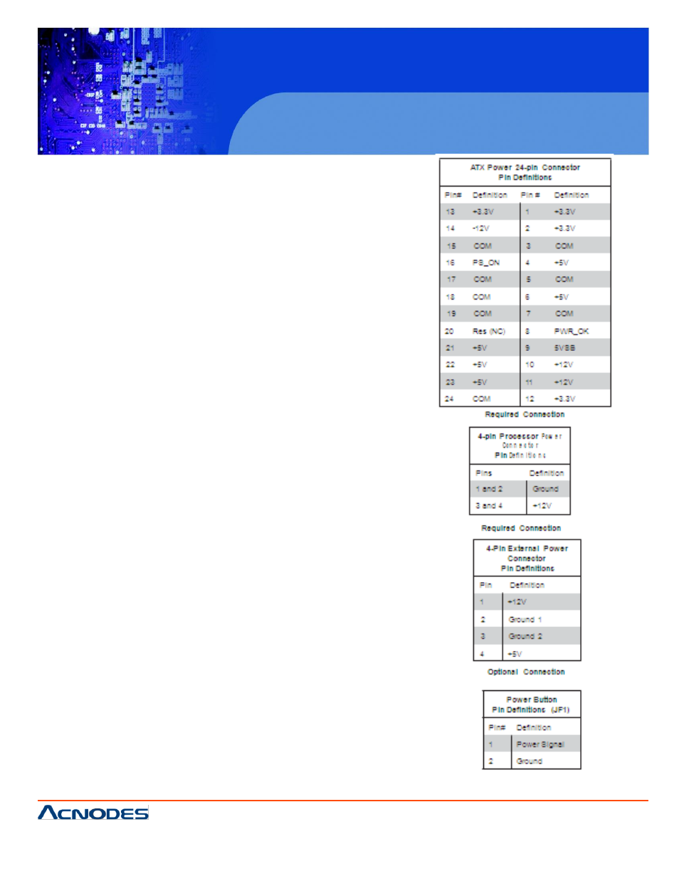
Main ATX Power Supply
Connector
The 24-pin main power connector (JPW1) is used to provide
power to the motherboard. This power connec- tor meets the
SSI EPS 12V specifica- tion. See the table on the right for
pin definitions.
Processor Power Connector
The 4-pin processor power connec- tor (J7) is also re-
quired to ensure adequate power to the processor. This
power connector meets the SSI EPS 12V specification. See
the table on the right for pin definitions.
External Power Connector
In addition to the 24-pin main power connector, the 4-pin
External Power connector at J8 is used to provide power to
external devices such as hard disks & CD-ROM drives.
This power connector supports 12V and 5V devices.
Power Button
The Power Button connection is located on pins 1 and 2 of
JF1. Momentarily contacting both pins will power on/off the
system. To turn off the power when set to suspend mode,
press the button for at least 4 seconds. Refer to the table on
the right for pin definitions.