Installation speciðcation 15. specification, 1 dimensions and connections, 2 wiring diagram – STIEBEL ELTRON HDB-E Si 01.11.2012 - 31.01.2013 User Manual
Page 26: 3 mixed water volume / outlet volume
26
| HDB-E Si
www.stiebel-eltron.com
INSTALLATION
SpeciÐcation
15. Specification
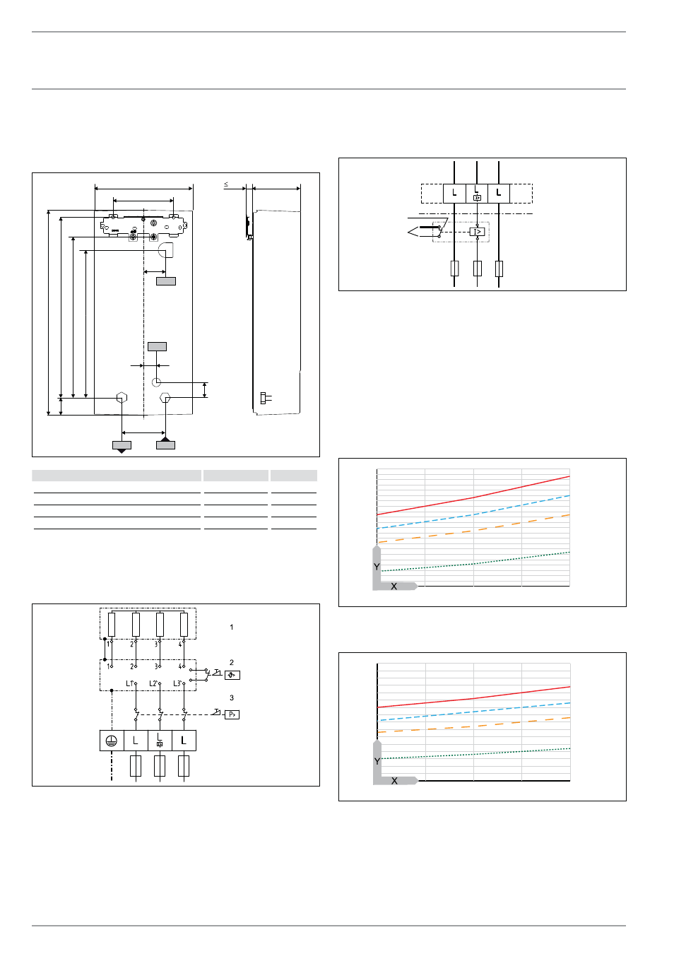
15.1 Dimensions and connections
b02
c01
c06
470
100
414
40
117
20
225
140
35
368
30
338
47
b03
D00000
2
3
6
0
9
b02 Entry electrical cables I
b03 Entry electrical cables II
c01
Cold water inlet
Male thread
G 1/2 A
c06 DHW
outlet
Male thread
G 1/2 A
15.2 Wiring
diagram
3/PE ~ 380 - 415 V
8
5
_0
2_0
2
_0
0
0
5
1 Bare wire heating system
2 High limit safety cut-out
3 Safety pressure limiter
Priority control with load shedding relay (LR 1-A)
See also chapter “Appliance description / Accessories”.
8
5
_0
2_0
2
_0
0
0
3_
2
1
1 Control cable to the contactor of the second appliance (e.g.
electric storage heater).
2 Control contact opens when switching the instantaneous
water heater on.
15.3 Mixed water volume / outlet volume
The values are relative to a rated voltage of 400 V. The mixed water
volume and outlet volume are subject to the available supply pres-
sure and the available mains voltage.
Available temperature approx. 38 °C in the shower, for hand wash-
ing, filling the bath etc.
6
10
14
4
5
6
7
8
9
10
11
12
13
14
15
4
3
2
1
84
_0
2_
0
2
_0
0
3
8
Outlet temperature approx. 55 °C for the kitchen sink and when
using thermostatic valves.
2
3
4
5
6
7
8
9
10
6
10
14
4
3
2
1
84
_0
2_
0
2
_0
0
3
9
X Cold water inlet temperature in °C
Y Mixed water volume / outlet volume in l/min
1 HDB-E 12 Si
2 HDB-E 18 Si
3 HDB-E 21 Si
4 HDB-E 24 Si