2 rear panel, 1 power connector, 3 leds – ZyXEL Communications ES-2024 Series User Manual
Page 40: Table 2 leds
Chapter 3 Hardware Overview
ES-2024 Series User’s Guide
40
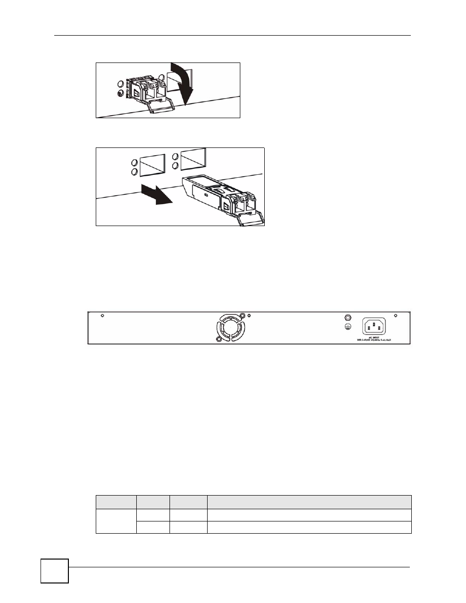
Figure 12 Opening the Transceiver’s Latch Example
2 Pull the transceiver out of the slot.
Figure 13 Transceiver Removal Example
3.2 Rear Panel
The following figure shows the rear panel of the Switch. The power receptacle is on the read
panel.
Figure 14 Rear Panel
3.2.1 Power Connector
Make sure you are using the correct power source as shown on the panel.
To connect the power to the Switch, insert the female end of power cord to the power
receptacle on the rear panel. Connect the other end of the supplied power cord to the power
source.
3.3 LEDs
The LEDs are located on the front panel. The following table describes the LEDs on the front
panel.
Table 2 LEDs
LED
COLOR
STATUS
DESCRIPTION
PWR
Green
On
The system is turned on.
Off
The system is off.
- ZyXEL Dimension GS-1116A (30 pages)
- ZyXEL Dimension ES-2108PWR (4 pages)
- DIMENSION ES-4024 (4 pages)
- MI-7526F (6 pages)
- ZyXEL Dimension ES-2048 (306 pages)
- DIMENSION ES-1016A (2 pages)
- ONU-6040B-21 (19 pages)
- HOMEBOUND TRIPLE PLAY DELIVERY ES-315-F (2 pages)
- IES-708-22 (6 pages)
- Version 1.03 (242 pages)
- ZyXEL Dimension ES-1552 (43 pages)
- ES-2108 (224 pages)
- ZyXEL Dimension ES-1124 (48 pages)
- 2-Slot 10GBase-CX4 10Gigabit Module EM-412 (18 pages)
- GS-105B/108B (48 pages)
- ES-4024A (128 pages)
- ETHERNET SWITCHES ES-1016 (2 pages)
- GS-4012F/4024 (363 pages)
- ZyXEL Dimension ES-2024 (195 pages)
- ZyXEL Dimension ES-2108 (277 pages)
- ZyXEL Dimension GS-3012F (237 pages)
- VES-1000 (155 pages)
- PoE-80 (23 pages)
- ES-1124 (30 pages)
- 4500 Series (7 pages)
- ES-3148 Series (362 pages)
- GS-3012F Series (300 pages)
- Ethernet-to-Fiber Media Converter MC1000-SFP-FP (34 pages)
- GS2200-24P (4 pages)
- ES-105A/108A (2 pages)
- ZyXEL Dimension GS-1016 (32 pages)
- EES-1024AF (99 pages)
- GS-4012 (462 pages)
- IES-6000 (100 pages)
- ES-315 (166 pages)
- ES-2108 Series (283 pages)
- ZyXEL Dimension ES-2024PWR (286 pages)
- GS-3012F/3012 (314 pages)
- GS-108B (48 pages)
- GS-105 (7 pages)
- GS-4012F (462 pages)
- VES-1616 (118 pages)
- A-6000 (23 pages)
- LAYER 3 ES-3124 (337 pages)
- GS-105A (2 pages)