5 communication interface, 1 remote contact, Communication interface – Toshiba 4200FA CT/XT User Manual
Page 30: Remote contact, Toshiba
TOSHIBA
4.5 Communication
Interface
4.5.1
Remote Contact
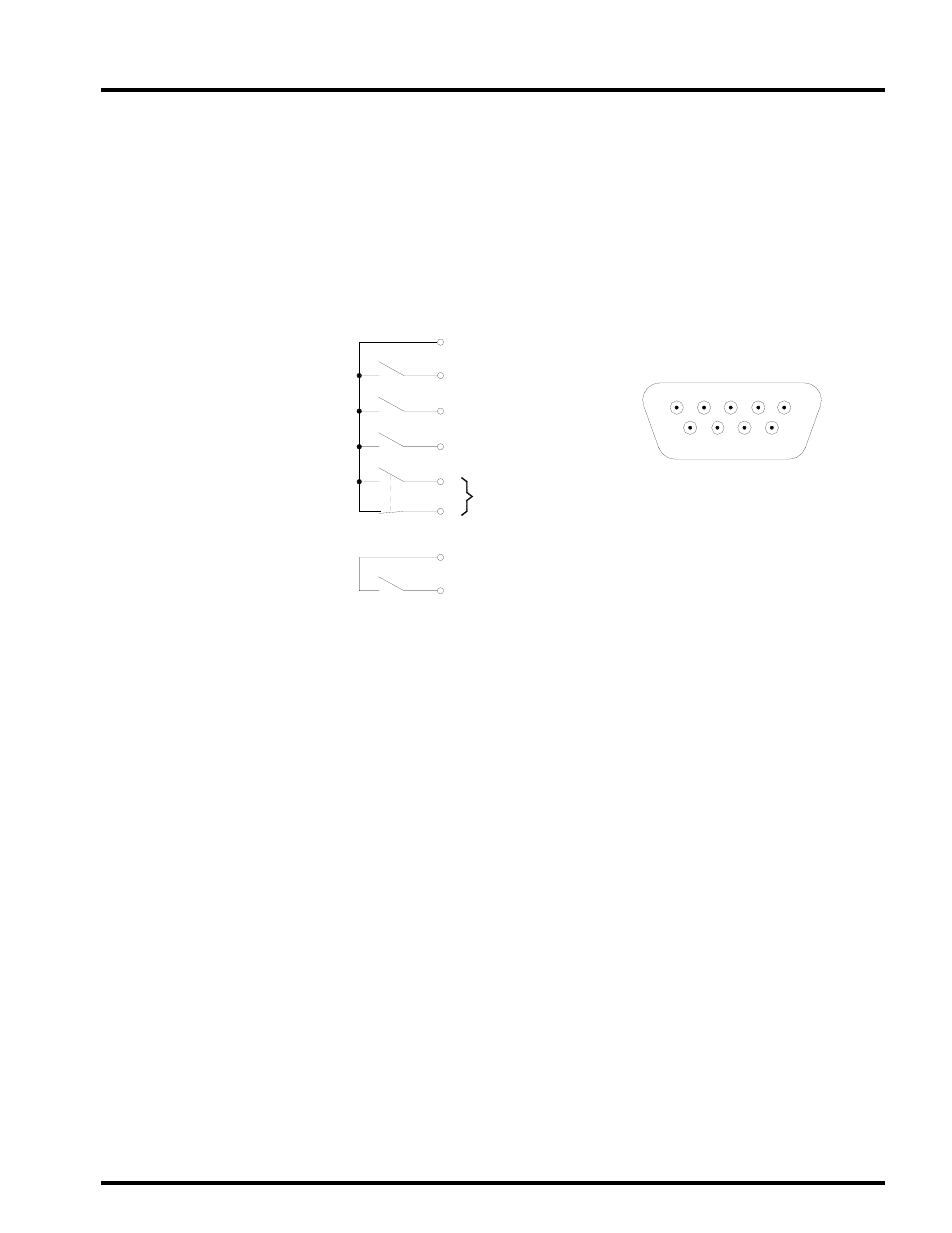
This interface is a standard feature and is available as dry switch contacts through a DB9
male connector located on the front of the UPS. The following schematic shows the
contact state and pin assignment for each signal and the associated DB9 connector pin-
out.
5 System Common
6 Bypass Active
Fault Signal Detect
1
2
8 UPS On-line
7 Battery Voltage Low
Battery Discharge
9
4
DB9 Male Connector Outline
(facing connector)
1 2 3 4 5
6 7 8 9
Notes:
1) Pin “switches” are shown in their inactive states. Example: (if battery voltage is low, pin 7 will be
connected to System Common).
2) Contacts are rated at 30 VDC, 0.1 amps; 125 VAC, 3 amps.
3) Pin number “3” is not used.
4200FA CT/XT User’s Manual
29
- Power Inverter (15 pages)
- 1800 (6 pages)
- TOSVERT VF-S11 (68 pages)
- Uninterruptible Power System G9000 (104 pages)
- Density (Consistency) Meter LQ500 (9 pages)
- MBSB80-225-43 (1 page)
- TOSNIC-7000S (53 pages)
- 1600EP Series (3 pages)
- 1500 (32 pages)
- TOSVERT VF-FS1 Series (16 pages)
- 4200FA XT1 (1 page)
- G3 Plus Pack (4 pages)
- Tosvert VF-A5 (149 pages)
- 1600 Series (3 pages)
- G9000 (100 pages)
- TEC EO1-33030 (54 pages)
- 1000 Series (2 pages)
- 1500 Plus (31 pages)
- G8000MM (6 pages)
- VT130G1 (99 pages)
- 4200FA Series (2 pages)
- VF-PS1 (10 pages)
- GX7 Series (6 pages)
- 4200FA XT (1 page)
- RMTI-EMD-HT (2 pages)
- W7 Series (6 pages)
- HX7 (6 pages)
- PDP002Z (18 pages)
- RELIABILITY IN MOTION 1700 (39 pages)
- 1700 Series (2 pages)
- G3 TOSVERT-130 (62 pages)
- B-852-TS12-QP (55 pages)
- 1000 (4 pages)
- E3 (7 pages)
- Adjustable Speed Drive H3 (122 pages)
- 55611-001 (2 pages)
- Black Gold Series (2 pages)
- Dura-Bull TX (6 pages)
- Current Relay RC803A-HP1 (19 pages)
- 1800 SERIES (2 pages)
- Isolated-Redundant UPS System (2 pages)
- Tosvert VF-AS1 (312 pages)
- RELIABILITY IN MOTION 1000 (54 pages)
- REMOTE-D (2 pages)
- 15-80KVA (2 pages)